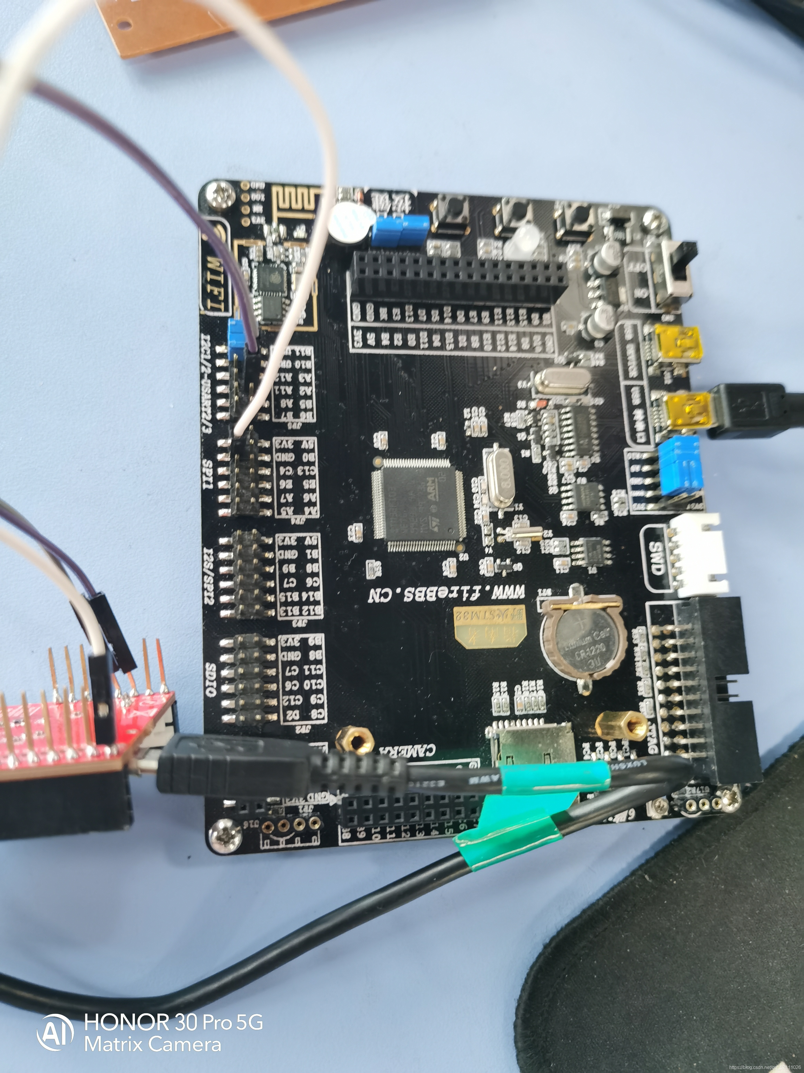
Openmv与stm32 的串口通信
前言
假期准备参加电赛,学习了openmv,openmv识别到的数据传到STM32,然后进行下一步的处理,为了实现来着之间的通信,花了很长时间,终于实现了,现在想想好像也挺简单的,哈哈哈哈,但是对于我这种小白还是有点难,大佬就不用看啦!!
防止以后忘记,来CSDN做一个笔记吧!!
openmv端
在openmv端主要的工作是对目标物体进行识别,然后将需要的数据通过打包,再使用串口发送个单片机。这里有几个关键的地方:
数据打包的格式:
data = ustruct.pack("<bbhhhhb", #格式为俩个字符俩个短整型(2字节) 0x2C, #帧头1 0x12, #帧头2 int(cx), # up sample by 4 #数据1 int(cy), # up sample by 4 #数据2 int(cw), # up sample by 4 #数据1 int(ch), # up sample by 4 #数据2 0x5B) uart.write(data); #必须要传入一个字节数组
打包的方式如上图所示,为了防止数据错误,需要加入两个数据帧头和一个 数据帧尾。
openmv传输的数据的形式
openmv只能传输十六进制的数据给STM32,否则STM32将收不到数据,结果就是单片机和openmv都能正常和电脑通信,但是两者结合就不能正常通信
十六进制数据的实现主要通过 bytearray ()这个函数,具体的格式如下:OUT_DATA =bytearray([0x2C,0x12,cx,cy,cw,ch,0x5B])
在openmv段主要的问题就是这两个地方,区域的串口的配置,以及数据发送数都是常规的,openmv还有一种数据格式,就是json字符串,都是我还没试过,以后再补上。
openmv端完整的源代码
from pyb import UART,LED
import json,ustruct,sensor,time

red_threshold  = (2, 12, -56, 2, -75, 14)#测试所用,白色,懒得该名称
sensor.reset() # Initialize the camera sensor.
sensor.set_pixformat(sensor.RGB565) # use RGB565.
sensor.set_framesize(sensor.QQVGA) # use QQVGA for speed.
sensor.skip_frames(10) # Let new settings take affect.
sensor.set_auto_whitebal(False) # turn this off.
clock = time.clock() # Tracks FPS.

uart = UART(3,115200)   #定义串口3变量
uart.init(115200, bits=8, parity=None, stop=1) # init with given parameters

'''寻找最大色块'''
def find_max(blobs):
    max_size=0
    for blob in blobs:
        if blob[2]*blob[3] > max_size:
            max_blob=blob
            max_size = blob[2]*blob[3]
    return max_blob
'''数据发送函数'''
def sending_data(cx,cy,cw,ch):
    global uart;
    #frame=[0x2C,18,cx%0xff,int(cx/0xff),cy%0xff,int(cy/0xff),0x5B];
    #data = bytearray(frame)
    data = ustruct.pack("<bbhhhhb",      #格式为俩个字符俩个短整型(2字节)
                   0x2C,                      #帧头1
                   0x12,                      #帧头2
                   int(cx), # up sample by 4   #数据1
                   int(cy), # up sample by 4    #数据2
                   int(cw), # up sample by 4    #数据1
                   int(ch), # up sample by 4    #数据2
                   0x5B)
    uart.write(data);   #必须要传入一个字节数组

while(True):
    clock.tick() # Track elapsed milliseconds between snapshots().
    img = sensor.snapshot() # Take a picture and return the image.

    blobs = img.find_blobs([red_threshold])
    if blobs:
        max_blob = find_max(blobs)
        img.draw_rectangle(max_blob.rect()) # rect
        img.draw_cross(max_blob.cx(), max_blob.cy()) # cx, cy
        cx=max_blob[5]
        cy=max_blob[6]
        cw=max_blob[2]
        ch=max_blob[3]
        OUT_DATA =bytearray([0x2C,0x12,cx,cy,cw,ch,0x5B])
        uart.write(OUT_DATA)
        print(OUT_DATA)
STM32 端
说到STM32 端真的是让我走了很多的弯路,就因为printf()重定向,刚开始用的方式有点问题,让我花了很多很多时间,导致串口调试助手一直收不到消息,还以为是板子坏了,最后发现是重定向的问题,这是两种方式:
经过验证后的正确方式:
# include "stdio.h"
int fputc(int ch ,FILE *f)
{
	//轮询方式发送一个字节数据
	HAL_UART_Transmit (&huart1 ,(uint8_t *)&ch , 1,HAL_MAX_DELAY );
	return ch ;
}
关键点:
串口接收中断 回调函数:
/*串口接收中断回调函数*/
void HAL_UART_RxCpltCallback(UART_HandleTypeDef *huart)
{
  uint16_t tempt  /*定义临时变量存放接受的数据*/;
  if(huart->Instance==USART2)
  {
    tempt=USART2_RXbuff;
    Openmv_Receive_Data(tempt);
		/*调运数据接收处理函数,每次进入中断都对数据进行理处
		,由于需要接收器个数据,因此要进入七次断理*/
  }
HAL_UART_Receive_IT(&huart2,(void *)&USART2_RXbuff,1);/*再次开启接收中断*/
}
最后的重新开启中断接收一定不能忘记;
数据读取的函数
openmv.c
#include "OpenMV.h"
#include "stdio.h"
#include "usart.h"
/*四个变量用于存放目标物体的中心坐标以及宽度,高度*/
static uint8_t  Cx=0,Cy=0,Cw=0,Ch=0;
/*数据接收函数*/
void Openmv_Receive_Data(int16_t Com_Data)
{
  /*循环体变量*/
  uint8_t i;
	/*计数变量*/
	static uint8_t RxCounter1=0;//计数
	/*数据接收数组*/
	static uint16_t RxBuffer1[10]={0};
	/*数据传输状态位*/
	static uint8_t RxState = 0;
	/*对数据进行校准,判断是否为有效数据*/
  if(RxState==0&&Com_Data==0x2C)  //0x2c帧头
		{

			RxState=1;
			RxBuffer1[RxCounter1++]=Com_Data;
      HAL_GPIO_WritePin(LED_GPIO_Port, LED_Pin, GPIO_PIN_SET);
		}

	else if(RxState==1&&Com_Data==0x12)  //0x12帧头
		{
      HAL_GPIO_WritePin(LED_GPIO_Port, LED_Pin, GPIO_PIN_RESET);
			RxState=2;
			RxBuffer1[RxCounter1++]=Com_Data;
		}
	else if(RxState==2)
		{

			RxBuffer1[RxCounter1++]=Com_Data;
			if(RxCounter1>=10||Com_Data == 0x5B)       //RxBuffer1接受满了,接收数据结束
				{
					RxState=3;
					Cx=RxBuffer1[RxCounter1-5];
					Cy=RxBuffer1[RxCounter1-4];
					Cw=RxBuffer1[RxCounter1-3];
					Ch=RxBuffer1[RxCounter1-2];
          printf("%d\r   ",Cx);
          printf("%d\r   ",Cy);
          printf("%d\r   ",Cw);
          printf("%d\r\n",Ch);
					}
			}

				else if(RxState==3)//检测是否接受到结束标志
				{
						if(RxBuffer1[RxCounter1-1] == 0x5B)
						{
									//RxFlag1 = 0;
									RxCounter1 = 0;
									RxState = 0;
						}
						else   //接收错误
						{
									RxState = 0;
									RxCounter1=0;
									for(i=0;i<10;i++)
									{
											RxBuffer1[i]=0x00;      //将存放数据数组清零
									}
						}
				}

				else   //接收异常
				{
						RxState = 0;
						RxCounter1=0;
						for(i=0;i<10;i++)
						{
								RxBuffer1[i]=0x00;      //将存放数据数组清零
						}
				}
      }
openmv.h
#ifndef __OpenMV_H
#define	__OpenMV_H

#include "stm32f1xx.h"

void  Openmv_Receive_Data(int16_t data);


#endif
主函数里面没什么太多的内容,主要是开启中断接收,以及一些变量的定义
  /* USER CODE BEGIN 2 */
HAL_UART_Receive_IT(&huart2,(void *)&USART2_RXbuff,1);
HAL_UART_Receive_IT(&huart1,(void *)&USART1_RXbuff,1);
  /* USER CODE END 2 */
/* USER CODE BEGIN PV */
uint8_t USART1_RXbuff;  // 接收缓冲区;
uint8_t USART2_RXbuff;
		uint8_t ch = 0;
cubemx 配置很简单

最后就是接线的问题啦!!

完成,收工,有问题就私聊吧!!!