使用寄存器点亮LED灯
一、LED原理
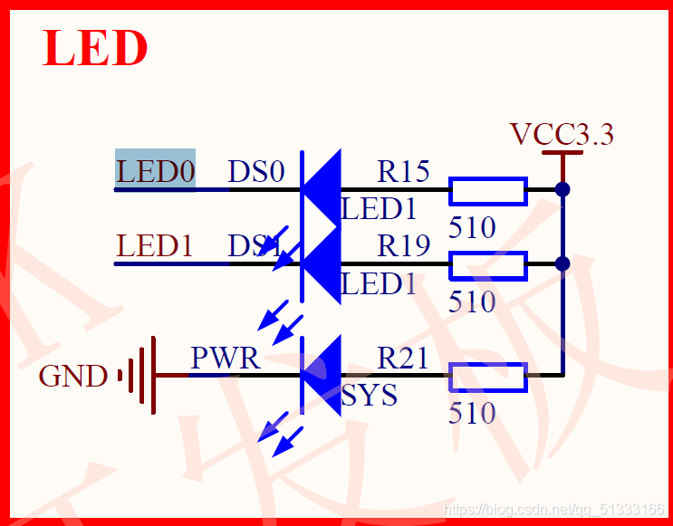
由电路图可以看到,LED0右端连接3.3高电平电压,左侧对应PB5端口。所以当PB5=0时,会形成从右向左的电流。LED灯点亮。


二、端口值的输出-(GPIOx_ODR) (x=A…E)
因为LED接的端口是PB5,所以对应了GPIOB_ODR

代码:
*( unsigned int * )0x40010C0C &= ~( 1 << 5 ) ;

- 0x40010C0C:在参考手册中查找存储器映射,可以查到GPIO寄存器的起始地址。GPIOB起始地址0x40010C00+ODR寄存器地址偏移0Ch(h表示16进制),所以为0x40010C0C
- ( unsigned int * )0x40010C0C &= ~( 1 << 5 ) :
等价于( unsigned int * )0x40010C0C &= ~(0010 0000)
等价于*( unsigned int * )0x40010C0C=(0000 0000)&(1101 1111)
等价于*( unsigned int * )0x40010C0C=1101 0000
操作中,常用 置位 |= ,清零 &=~
三、使端口模式为输出模式
每四位对应ODR中的1位,所以对于PB5来说,就是CRL中的20,21,22,23四位控制,要想使PB5端口为输出电压模式,要将CNF置为00,MODE置为01,偏移地址为0x00,实际地址即为0x40010C00

*( unsigned int * )0x40010C00 |=( (1) << (4*5) ) ;
四、打开端口时钟控制
时钟相当于单片机的心脏,任何程序的运行需要先将时钟使能


PB端口是第3位控制
*( unsigned int * )0x40021018 |=( 1 << 3 )
所以在RCC寄存器中,第3位的值要置1,才能开启B时钟,端口才能正常工作
完整代码
#include "stm32f10x.h"

int main(void)
{
	*( unsigned int * )0x40021018 |=( 1 << 3  )	;									//打开GPIO端口的时钟

	*( unsigned int * )0x40010C00 |=( (1) << (4*5) ) ;						// 配置IO口为输出

	*( unsigned int * )0x40010C0C &= ~( 1 << 5 ) ;								// 控制 ODR 寄存器


}


//置位 |=  ,清0 &=~

void SystemInit(void)
{
	//函数体为空,为了不报错
}