开始之前我们需要了解的是完成闭环控制输出任务前提是必须要有printf输出功能和PWM输出功能。
1)其中printf功能是为了在最后阶段,监测实时的PWM值,检测是否实现闭环控制。
关于printf功能的实现可参考教程4的内容:
STM32CubeIDE自平衡小车教程4.配置串口并实现字符的输出
2)PWM输出功能是为了实现最后车轮能按照设定的转速转动。
关于PWM输出功能的实现可参考教程5的内容:
STM32CubeIDE自平衡小车教程5.直流电机转速开环控制
以下是实现电机转速闭环控制的步骤:
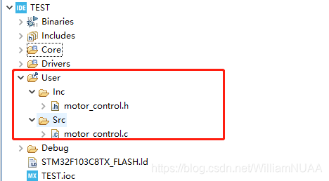
1.打开上节的工程文件,在工程文件中新加一个User文件夹,在文件夹目录下新建Src和Inc文件夹,并分别添加.c文件和.h文件并命名为motor_control.c和motor_control.h


2.在motor_control.c文件中加入以下代码:
#include "main.h"

float SpeedKp = 10.0, SpeedKi = 1, SpeedKd = 0;

int Motor1SpeedClosedControl(int Encoder,int Target)
{
	static float Error,ErrorPrev,ErrorLast,PWM;

	Error = Target - Encoder;

	PWM += SpeedKp*(Error - ErrorPrev) + SpeedKi*Error + SpeedKd*(Error - 2*ErrorPrev + ErrorLast);

	ErrorLast = ErrorPrev;
	ErrorPrev = Error;

	if(PWM >= 100) PWM = 100;
	if(PWM <= -100) PWM = -100;

	return PWM;
}

void SetMotor1Direction(int Pwm)//设置电机方向
{
if(Pwm < 0)//反转
{
HAL_GPIO_WritePin(BIN1_GPIO_Port, BIN1_Pin, GPIO_PIN_RESET);
HAL_GPIO_WritePin(BIN2_GPIO_Port, BIN2_Pin, GPIO_PIN_SET);
Pwm = (-Pwm);//如果计算值是负值,先取负得正,因为PWM寄存器只能是正值
__HAL_TIM_SET_COMPARE(&htim2, TIM_CHANNEL_4, Pwm);
}else
{
HAL_GPIO_WritePin(BIN1_GPIO_Port, BIN1_Pin, GPIO_PIN_SET);
HAL_GPIO_WritePin(BIN2_GPIO_Port, BIN2_Pin, GPIO_PIN_RESET);
__HAL_TIM_SET_COMPARE(&htim2, TIM_CHANNEL_4, Pwm);
}
}

int Motor2SpeedClosedControl(int Encoder,int Target)
{
	static float Error,ErrorPrev,ErrorLast,PWM;

	Error = Target - Encoder;

	PWM += SpeedKp*(Error - ErrorPrev) + SpeedKi*Error + SpeedKd*(Error - 2*ErrorPrev + ErrorLast);

	ErrorLast = ErrorPrev;
	ErrorPrev = Error;

	if(PWM >= 100) PWM = 100;
	if(PWM <= -100) PWM = -100;

	return PWM;
}

void SetMotor2Direction(int Pwm)//设置电机方向
{
	if(Pwm < 0)//反转
	{
	HAL_GPIO_WritePin(AIN1_GPIO_Port, AIN1_Pin, GPIO_PIN_SET);
	HAL_GPIO_WritePin(AIN2_GPIO_Port, AIN2_Pin, GPIO_PIN_RESET);
	Pwm = (-Pwm);//如果计算值是负值,先取负得正,因为PWM寄存器只能是正值
	__HAL_TIM_SET_COMPARE(&htim2, TIM_CHANNEL_3, Pwm);
	}
	else
	{
	HAL_GPIO_WritePin(AIN1_GPIO_Port, AIN1_Pin, GPIO_PIN_RESET);
	HAL_GPIO_WritePin(AIN2_GPIO_Port, AIN2_Pin, GPIO_PIN_SET);
	__HAL_TIM_SET_COMPARE(&htim2, TIM_CHANNEL_3, Pwm);
	}
}
3.在motor_control.h文件中加入以下代码:
int Motor1SpeedClosedControl;
int Motor2SpeedClosedControl;
void SetMotor1Direction(int Pwm);
void SetMotor2Direction(int Pwm);
4.在main.c文件中在上节代码的基础中添加如下代码:
	HAL_TIM_Encoder_Start(&htim3,TIM_CHANNEL_ALL);
	HAL_TIM_Encoder_Start(&htim4,TIM_CHANNEL_ALL);
?5.打开在Core文件夹下Src文件夹中的stm32f1xx_it.c文件,下拉找到void SysTick_Handler(void),并加入以下代码(要加在CODE BEGIN和CODE END中间):
static unsigned char Timer5msCounter;
	static int Motor1Speed;
	static int Motor1PWM;
	static int Motor2Speed;
	static int Motor2PWM;

	Timer5msCounter++;
	  if(Timer5msCounter >=5)//每5s一个周期
	  {
		  Timer5msCounter = 0;
		  Motor2Speed = GetTim4Encoder();
		  Motor1Speed = GetTim3Encoder();

		  printf("M1Speed = %d \n", Motor1Speed);
		  printf("M2Speed = %d \n", Motor2Speed);

		  Motor1PWM = Motor1SpeedClosedControl(Motor1Speed,-20);
		  Motor2PWM = Motor2SpeedClosedControl(Motor2Speed,30);

		  SetMotor1Direction(Motor1PWM);
		  SetMotor2Direction(Motor2PWM);
      }
?6.在工程文件目录下的Core文件夹下添加Inc和Src文件夹,并添加encoder.c文件和encoder.h文件。
在encoder.c文件下添加以下代码:
#include "tim.h"//包含tim头文件
#include "encoder.h"

int iTim4Encoder;//存放从TIM4定时器读出来的编码器脉冲
int iTim3Encoder;

int GetTim4Encoder(void)//获取TIM4定时器读出来的编码器脉冲
{
	iTim4Encoder = (short)(__HAL_TIM_GET_COUNTER(&htim4));//先读取脉冲数
	__HAL_TIM_SET_COUNTER(&htim4,0);//再计数器清零
	return iTim4Encoder;//返回脉冲数
}

int GetTim3Encoder(void)//获取TIM4定时器读出来的编码器脉冲
{
	iTim3Encoder = (short)(__HAL_TIM_GET_COUNTER(&htim3));//先读取脉冲数
	__HAL_TIM_SET_COUNTER(&htim3,0);//再计数器清零
	return iTim3Encoder;//返回脉冲数
}
在encoder.h文件下添加以下代码:
int GetTim4Encoder(void);//声明函数
int GetTim3Encoder(void);7.点击编译并进行烧录,完成PID速度闭环控制任务。可在在stm32f1xx_it.c中更改小车M1和M2电机的脉冲速度,正数转向为正向,负数转向为反向,并在调试器中接收小车的脉冲速度。(需要打开小车电源开关)
例如此时设置M1电机脉冲速度为-20,M2电机脉冲速度为40。

打开串口数据调试工具,可查看小车实时输出的PWM值:

STM32CubeIDE电机闭环转速控制效果展示