运动控制
简单的FOC库有两个主要参数,用于定义要使用的运动控制架构(并且每个参数都可以实时修改):
转矩控制方式
Simple?FOC库中实现了三种转矩控制类型:
- 电压 -?
TorqueControlType::voltage - 直流电流 -?
TorqueControlType::dc_current - FOC 电流 -?
TorqueControlType::foc_current
?? 如果选择开环运动控制,则不使用此参数。
并且可以通过更改电机属性来设置它们torque_controller。
// set torque mode to be used
// TorqueControlType::voltage    ( default )
// TorqueControlType::dc_current
// TorqueControlType::foc_current
motor.torque_controller = TorqueControlType::foc_current;
有关不同扭矩模式的更深入解释
转矩控制方式
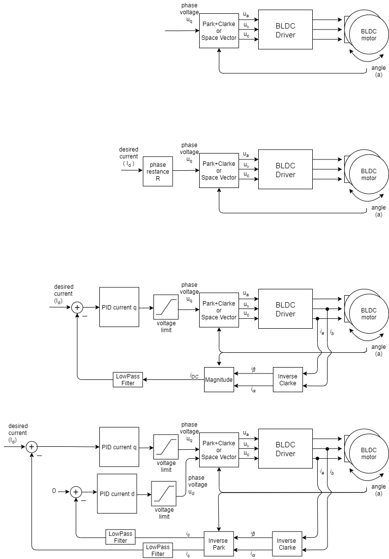
?
简单的FOC库让您可以选择使用 3 种不同的扭矩控制策略:
1. 电压模式 -?voltage
通过电压进行转矩控制是最基本的转矩控制类型,它为您提供了对 BLDC 电机的抽象,以便您可以将其作为直流电机进行控制。它基于电流与电压成正比的原理(忽略电流动态),因此不需要任何电流检测硬件。有关此方法的更多信息,请访问我们的深入挖掘部分。这种扭矩控制方法将能够在任何 BLDC 驱动板上工作,无论它是否具有电流感应。
使用电压的转矩控制
这种转矩控制方法允许您运行 BLDC 电机,因为它是简单的直流电机,在这里设定的目标电机电压Uq?和FOC算法计算所需的相电压ua?,ub?and?uc?为运行平稳。此模式通过以下方式启用:
// voltage torque control mode
motor.torque_controller = TorqueControlType::voltage;
它是如何工作的
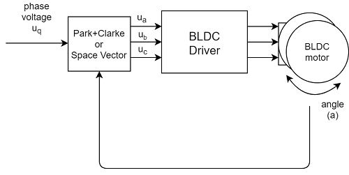
电压控制算法从位置传感器读取角度a并从用户处获取目标U?q电压值,并使用 FOC 算法为电机设置适当的u?a、u?b和u?c电压。FOC 算法确保这些电压在电机转子中产生与其永磁磁场90 度偏移的磁力,从而保证最大扭矩,这称为换向。
假设是电机中产生的扭矩与电压成正比,因为Uq由?用户设置r。最大扭矩对应于由可用电源电压决定的最大Uq,而最小扭矩当然是Uq?= 0。
如果用户提供电机的相电阻值,用户可以设置所需的电流?Id?,库会自动计算出合适的电压Uq。这可以通过例如构造函数来完成
// BLDCMotor(pole pair number, phase resistance)
BLDCMotor motor = BLDCMotor( 11, 2.5 );
或者只是设置参数:
motor.phase_resistance = 2.5; // ex. 2.5 Ohms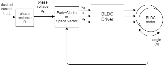
配置参数
这个控制回路是非常基本的,它实际上没有任何配置参数。
转矩控制示例代码
基于电压的转矩控制和通过串行命令接口设置目标电流的简单示例。
#include <SimpleFOC.h>

// BLDC motor & driver instance
BLDCMotor motor = BLDCMotor(11);
BLDCDriver3PWM driver = BLDCDriver3PWM(9, 5, 6, 8);

// encoder instance
Encoder encoder = Encoder(2, 3, 500);
// channel A and B callbacks
void doA(){encoder.handleA();}
void doB(){encoder.handleB();}

// instantiate the commander
Commander command = Commander(Serial);
void doTarget(char* cmd) { command.variable(&motor.target, cmd); }

void setup() {

  // initialize encoder sensor hardware
  encoder.init();
  encoder.enableInterrupts(doA, doB);
  // link the motor to the sensor
  motor.linkSensor(&encoder);

  // driver config
  // power supply voltage [V]
  driver.voltage_power_supply = 12;
  driver.init();
  // link driver
  motor.linkDriver(&driver);

  // set the torque control type
  motor.phase_resistance = 12.5; // 12.5 Ohms
  motor.torque_controller = TorqueControlType::voltage;
  // set motion control loop to be used
  motor.controller = MotionControlType::torque;

  // use monitoring with serial
  Serial.begin(115200);
  // comment out if not needed
  motor.useMonitoring(Serial);

  // initialize motor
  motor.init();
  // align sensor and start FOC
  motor.initFOC();

  // add target command T
  command.add('T', doTarget, "target current");

  Serial.println(F("Motor ready."));
  Serial.println(F("Set the target current using serial terminal:"));
  _delay(1000);
}

void loop() {

  // main FOC algorithm function
  motor.loopFOC();

  // Motion control function
  motor.move();

  // user communication
  command.run();
}
?==================================================================================================================================================
2. 直流电流模式 -?dc_current
直流电流控制模式使您可以像控制直流电机一样控制 BLDC 电机的电流。电流感测用于获得电机所汲取的电流及其方向的总体大小,并且假设扭矩与总电流成正比。这种方法的好处是可以非常精确地控制设置到 BLDC 电机的真实电流,对于性能较低的微控制器(例如 Atmega328 系列)执行速度更快、更稳定。
使用直流电流的转矩控制
该控制回路允许您运行 BLDC 电机,因为它是电流控制的直流电机。这种扭矩控制算法需要电流检测硬件。用户设置目标电流?Id?到 FOC 算法中, FOC算法计算出维持运行所必要的相电压ua?,ub?and?uc,此模式通过以下方式启用:
// DC current torque control mode
motor.torque_controller = TorqueControlType::dc_current;
它是如何工作的
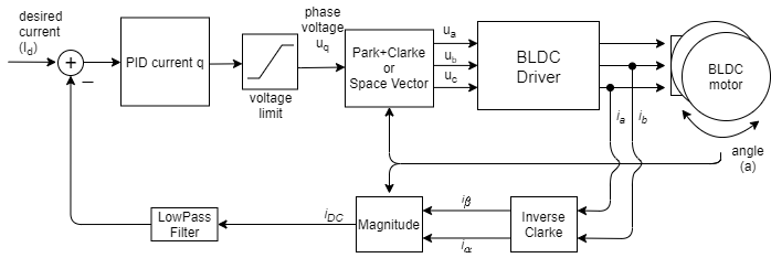
直流电流转矩控制算法读取 BLDC 电机的相电流(通常为?ia?and?ib)。此外,该算法从位置传感器读取转子角度α。使用the Inverse Clarke and Park(simplified) 变换将相电流转换为直流电流iDC。PID 控制器,使用目标电流值I?d和测得的i?DC,?计算出适当电压值U?q ,并设置电机,U?d保持为 0。最后 FOC 算法设置适当的电机电压u?a?,?ub和u?c。FOC 算法确保这些电压在电机转子中产生与其永磁磁场90 度偏移的磁力,从而保证最大扭矩,这称为换向。
这种转矩控制模式的假设是电机中产生的转矩与电机汲取的直流电流i?DC成正比(i?DC?=?i?q)。因此,通过控制这个电流,我们用户可以控制扭矩值。该假设仅适用于低速,对于更高的速度,电流的i?d分量变得更高,并且i?DC?=?i?q不再成立。
配置参数
为了使该回路平稳运行,用户需要配置 PID 控制器参数 tehPID_current_q和低通滤波器LPF_current_q时间常数。
// PID parameters - default
motor.PID_current_q.P = 5;                       // 3    - Arduino UNO/MEGA
motor.PID_current_q.I = 1000;                    // 300  - Arduino UNO/MEGA
motor.PID_current_q.D = 0;
motor.PID_current_q.limit = motor.voltage_limit;
motor.PID_current_q.ramp = 1e6;                  // 1000 - Arduino UNO/MEGA
// Low pass filtering - default
LPF_current_q.Tf= 0.005;                         // 0.01 - Arduino UNO/MEGA
转矩控制示例代码
使用串联电流传感器并通过串行命令接口设置目标值的基于直流电流的扭矩控制的简单示例。
#include <SimpleFOC.h>
// BLDC motor & driver instance
BLDCMotor motor = BLDCMotor(11);
BLDCDriver3PWM driver = BLDCDriver3PWM(9, 5, 6, 8);
// encoder instance
Encoder encoder = Encoder(2, 3, 500);
// channel A and B callbacks
void doA(){encoder.handleA();}
void doB(){encoder.handleB();}
// current sensor
InlineCurrentSense current_sense = InlineCurrentSense(0.01, 50.0, A0, A2);
// instantiate the commander
Commander command = Commander(Serial);
void doTarget(char* cmd) { command.variable(&motor.target, cmd); }
void setup() {
// initialize encoder sensor hardware
encoder.init();
encoder.enableInterrupts(doA, doB);
// link the motor to the sensor
motor.linkSensor(&encoder);
// driver config
// power supply voltage [V]
driver.voltage_power_supply = 12;
driver.init();
// link driver
motor.linkDriver(&driver);
// current sense init hardware
current_sense.init();
// link the current sense to the motor
motor.linkCurrentSense(¤t_sense);
// set torque mode:
motor.torque_controller = TorqueControlType::dc_current;
// set motion control loop to be used
motor.controller = MotionControlType::torque;
// foc current control parameters (Arduino UNO/Mega)
motor.PID_current_q.P = 5;
motor.PID_current_q.I= 300;
motor.LPF_current_q.Tf = 0.01;
// use monitoring with serial
Serial.begin(115200);
// comment out if not needed
motor.useMonitoring(Serial);
// initialize motor
motor.init();
// align sensor and start FOC
motor.initFOC();
// add target command T
command.add('T', doTarget, "target current");
Serial.println(F("Motor ready."));
Serial.println(F("Set the target current using serial terminal:"));
_delay(1000);
}
void loop() {
// main FOC algorithm function
motor.loopFOC();
// Motion control function
motor.move();
// user communication
command.run();
}==================================================================================================================================================
3.FOC电流模式 -?foc_current
FOC 电流控制是唯一真正的转矩控制方法。它控制电流向量的两个分量q和d。假设转矩与q电流分量成正比,并且控制电流分量d保持等于 0。
比较
| 转矩控制型 | 优点 | 缺点 |
|---|---|---|
| 电压 | ?? 非常简单和快速 ?? 任何 MCU 都具有良好的性能?? 低速时非常流畅 ?? 无需电流感应 | ? 在高速时不是最佳的 ? 无法控制真正的电流消耗 ? 扭矩是近似值(低速时误差很小) |
| 直流电流 | ?? 可以控制真正的电流消耗 ?? 适用于低性能 MUC ?? 限流 | ? 执行起来更复杂(更慢) ? 可以实现比电压模式更低的速度 ? 扭矩近似(低速时误差小) ? 需要电流感应 |
| FOC电流 | ?? 真正的扭矩控制(任何速度) ?? 可以控制真正的电流消耗 ?? 在更高的速度下非常有效 ?? 电流限制 | ? 执行起来最复杂(最慢) ? 不适合低性能 MCU(可能变得不稳定) ? 需要电流检测 |
使用 FOC 电流进行转矩控制
这种扭矩控制模式允许您对 BLDC 电机进行真正的扭矩控制,它需要电流感应才能做到这一点。用户设置目标电流I?d到FOC算法库,计算必要的相电压u?a、u?b和u?c,通过测量相电流(i?a、i?b和i?c)和转子角a来以维持运转。.?此模式通过以下方式启用:
// FOC current torque control mode
motor.torque_controller = TorqueControlType::foc_current;
它是如何工作的

FOC 电流转矩控制算法读取 BLDC 电机的相电流(通常为i?a和i?b)。此外,该算法从位置传感器读取转子角度α。使用?Inverse Clarke and Park变换将相电流转换为d电流i?d和q电流i?q。使用目标电流值I?d和测量的电流i?q和i?d,每个轴的 PID 控制器计算适当的电压U?q和U?d设置到电机,保持i?q?=?I?d和i?d?=0。最后使用 Park+Clarke(或 SpaceVector)变换,FOC 算法为电机设置适当的u?a、u?b和u?c电压。通过测量相电流,此转矩控制算法可确保这些电压在电机转子中产生适当的电流和磁力,并与其永磁场正好90 度偏移,从而保证最大转矩,这称为换向。
电机中产生的扭矩与 q 轴电流i?q成正比,使这种扭矩控制模式成为 BLDC 电机的真正扭矩控制。
配置参数
为了使该回路平稳运行,用户需要配置 PID 控制器参数 tehPID_current_q和低通滤波器LPF_current_q时间常数。
// Q axis
// PID parameters - default
motor.PID_current_q.P = 5;                       // 3    - Arduino UNO/MEGA
motor.PID_current_q.I = 1000;                    // 300  - Arduino UNO/MEGA
motor.PID_current_q.D = 0;
motor.PID_current_q.limit = motor.voltage_limit;
motor.PID_current_q.ramp = 1e6;                  // 1000 - Arduino UNO/MEGA
// Low pass filtering - default
LPF_current_q.Tf= 0.005;                         // 0.01 - Arduino UNO/MEGA

// D axis
// PID parameters - default
motor.PID_current_d.P = 5;                       // 3    - Arduino UNO/MEGA
motor.PID_current_d.I = 1000;                    // 300  - Arduino UNO/MEGA
motor.PID_current_d.D = 0;
motor.PID_current_d.limit = motor.voltage_limit;
motor.PID_current_d.ramp = 1e6;                  // 1000 - Arduino UNO/MEGA
// Low pass filtering - default
LPF_current_d.Tf= 0.005;                         // 0.01 - Arduino UNO/MEGA
转矩控制示例代码
使用串联电流传感器并通过串行命令接口设置目标值的基于 FOC 电流的扭矩控制的简单示例。
#include <SimpleFOC.h>
// BLDC motor & driver instance
BLDCMotor motor = BLDCMotor(6);
BLDCDriver3PWM driver = BLDCDriver3PWM(9, 5, 6, 8);
// encoder instance
Encoder encoder = Encoder(2, 3, 4096);
// channel A and B callbacks
void doA(){encoder.handleA();}
void doB(){encoder.handleB();}
// current sensor
InlineCurrentSense current_sense = InlineCurrentSense(0.01, 50.0, A0, A2);
// instantiate the commander
Commander command = Commander(Serial);
void doTarget(char* cmd) { command.variable(&motor.target, cmd); }
void setup() {
// initialize encoder sensor hardware
encoder.init();
encoder.enableInterrupts(doA, doB);
// link the motor to the sensor
motor.linkSensor(&encoder);
// driver config
// power supply voltage [V]
driver.voltage_power_supply = 12;
driver.init();
// link driver
motor.linkDriver(&driver);
// current sense init hardware
current_sense.init();
// link the current sense to the motor
motor.linkCurrentSense(¤t_sense);
// set torque mode:
motor.torque_controller = TorqueControlType::foc_current;
// set motion control loop to be used
motor.controller = MotionControlType::torque;
// foc current control parameters (Arduino UNO/Mega)
motor.PID_current_q.P = 5;
motor.PID_current_q.I= 300;
motor.PID_current_d.P= 5;
motor.PID_current_d.I = 300;
motor.LPF_current_q.Tf = 0.01;
motor.LPF_current_d.Tf = 0.01;
// use monitoring with serial
Serial.begin(115200);
// comment out if not needed
motor.useMonitoring(Serial);
// initialize motor
motor.init();
// align sensor and start FOC
motor.initFOC();
// add target command T
command.add('T', doTarget, "target current");
Serial.println(F("Motor ready."));
Serial.println(F("Set the target current using serial terminal:"));
_delay(1000);
}
void loop() {
// main FOC algorithm function
motor.loopFOC();
// Motion control function
motor.move();
// user communication
command.run();
}==================================================================================================================================================
运动控制方式
简单的FOC库实现了两种情况的运动控制:
闭环运动控制
Simple?FOC库中实现了三种闭环运动控制类型:
- 扭矩 -?
MotionControlType::torque - 速度 -?
MotionControlType::velocity - 角度 -?
MotionControlType::angle
它们可以通过改变电机controller参数来设置。
// set motion control loop to be used
// MotionControlType::torque
// MotionControlType::velocity
// MotionControlType::angle
motor.controller = MotionControlType::angle;
有关不同闭环运动控制回路的更深入解释
运动控制

simple?FOC库让您可以选择使用 3 种不同的闭环运动控制策略:
您可以通过更改motor.controller变量来设置它。如果您想控制电机角度,您将设置controller为MotionControlType::angle,如果您通过电压或电流使用寻求 BLDC 电机的扭矩MotionControlType::torque,如果您希望控制电机角速度MotionControlType::velocity。
// set FOC loop to be used
// MotionControlType::torque
// MotionControlType::velocity
// MotionControlType::angle
motor.controller = MotionControlType::angle;
转矩控制回路
simple?FOC库让您可以选择使用 3 种不同的扭矩控制策略:
简而言之,电压控制模式是电机扭矩控制的最简单近似,它非常基本,可以在任何电机+驱动器+单片机组合上运行。直流电流模式是电机扭矩近似的下一步,它比电压模式精确得多,但需要电流感应和更强大的微控制器。FOC 电流模式是控制电机的真实扭矩,它不是近似值,它还需要电流传感器,甚至比直流电流模式还需要更多的处理能力。请参阅扭矩模式文档中的深入解释。
启用此运动控制模式,将controller参数设置为:
// torque control loop
motor.controller = MotionControlType::torque;如果使用电压控制模式并且用户没有向电机提供相电阻参数,则转矩控制回路的输入将是目标电压U?q:
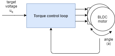
如果使用基于电流的转矩控制模式(DC 电流或 FOC 电流)之一,则控制回路中的输入将是目标电流i?q。如果用户向电机类提供相电阻值,则在电压模式下也是如此。

?扭矩控制回路用作所有其他运动控制回路的基础,有关蓝色框内容的更多信息,请查看扭矩模式文档。
配置参数
根据您希望使用的扭矩控制类型,您需要考虑不同的参数。
- 电压模式- 最简单的一种 - 除了可能之外没有参数
motor.phase_resistance - 直流电流模式- 1xPID 控制器 + 1xLPF
- FOC 电流模式- 2xPID 控制器 + 2xLPF 滤波器
现在,让我们看一个例子!
电压控制示例
您可以通过运行示例来测试此算法voltage_control.ino。
在这里,我们提供了一个使用电压控制程序和完整运动控制配置的扭矩示例。该程序使用 FOC 算法为电机设置2V 的目标U?q电压。由于相电阻参数不可用,电机目标将以伏特为单位。
#include <SimpleFOC.h>

// BLDC motor & driver instance
BLDCMotor motor = BLDCMotor(11);
BLDCDriver3PWM driver = BLDCDriver3PWM(9, 5, 6, 8);

// encoder instance
Encoder encoder = Encoder(2, 3, 500);
// channel A and B callbacks
void doA(){encoder.handleA();}
void doB(){encoder.handleB();}

void setup() {

  // initialize encoder sensor hardware
  encoder.init();
  encoder.enableInterrupts(doA, doB);
  // link the motor to the sensor
  motor.linkSensor(&encoder);

  // driver config
  // power supply voltage [V]
  driver.voltage_power_supply = 12;
  driver.init();
  // link driver
  motor.linkDriver(&driver);

  // set the torque control type
  motor.torque_controller = TorqueControlType::voltage;
  // set motion control loop to be used
  motor.controller = MotionControlType::torque;

  // use monitoring with serial
  Serial.begin(115200);
  // comment out if not needed
  motor.useMonitoring(Serial);

  // initialize motor
  motor.init();
  // align sensor and start FOC
  motor.initFOC();

  Serial.println(F("Motor ready."));
  Serial.println(F("Target voltage is 2V"));
  _delay(1000);
}

void loop() {

  // main FOC algorithm function
  motor.loopFOC();

  // Motion control function
  motor.move(2);
}
如果我们将 pahse 电阻添加到BLDCMotor类的构造函数中,则电机目标将以安培为单位。
#include <SimpleFOC.h>

// BLDC motor & driver instance
BLDCMotor motor = BLDCMotor(11, 12.34); // 12.34 Ohms
BLDCDriver3PWM driver = BLDCDriver3PWM(9, 5, 6, 8);

// encoder instance
Encoder encoder = Encoder(2, 3, 500);
// channel A and B callbacks
void doA(){encoder.handleA();}
void doB(){encoder.handleB();}

void setup() {

  // initialize encoder sensor hardware
  encoder.init();
  encoder.enableInterrupts(doA, doB);
  // link the motor to the sensor
  motor.linkSensor(&encoder);

  // driver config
  // power supply voltage [V]
  driver.voltage_power_supply = 12;
  driver.init();
  // link driver
  motor.linkDriver(&driver);

  // set the torque control type
  motor.torque_controller = TorqueControlType::voltage;
  // set motion control loop to be used
  motor.controller = MotionControlType::torque;

  // use monitoring with serial
  Serial.begin(115200);
  // comment out if not needed
  motor.useMonitoring(Serial);

  // initialize motor
  motor.init();
  // align sensor and start FOC
  motor.initFOC();

  Serial.println(F("Motor ready."));
  Serial.println(F("Target current is 0.5Amps"));
  _delay(1000);
}

void loop() {

  // main FOC algorithm function
  motor.loopFOC();

  // Motion control function
  motor.move(0.5);
}
===========================================================================
速度控制回路
该控制回路允许您以所需的速度旋转电机。此模式通过以下方式启用:
// set velocity motion control loop
motor.controller = MotionControlType::velocity;您可以通过运行motion_control/velocity_motion_control/文件夹中的示例来测试此算法。
这个怎么运作
速度控制关闭了扭矩控制周围的控制回路,无论它是哪一个。如果是没有设置相电阻的电压模式,速度运动控制将使用电压U?q?::

如果是电流转矩控制模式(FOC 或直流电流)或提供相电阻的电压模式中的任何一种,速度运动控制将设置目标电流i?q:

速度控制是通过在转矩控制回路中添加一个 PID 速度控制器来实现的。PID 控制器读取电机速度v,将其过滤为v?f并将转矩目标(u?q电压或i?q电流)设置到转矩控制回路,使其达到并保持由用户设置的目标速度v?d。
控制器参数
要调整此控制回路,您可以将参数设置为角度 PID 控制器和速度测量低通滤波器。
// controller configuration based on the control type
// velocity PID controller parameters
// default P=0.5 I = 10 D = 0
motor.PID_velocity.P = 0.2;
motor.PID_velocity.I = 20;
motor.PID_velocity.D = 0.001;
// jerk control using voltage voltage ramp
// default value is 300 volts per sec  ~ 0.3V per millisecond
motor.PID_velocity.output_ramp = 1000;

// velocity low pass filtering
// default 5ms - try different values to see what is the best.
// the lower the less filtered
motor.LPF_velocity.Tf = 0.01;

// setting the limits
// either voltage
motor.voltage_limit = 10; // Volts - default driver.voltage_limit
// of current
motor.current_limit = 2; // Amps - default 0.2Amps
PID 控制器的参数是比例增益P、积分增益I、微分增益D和output_ramp。
- 一般来说,通过提高比例增益
P,您的电机控制器将更具反应性,但过多会使其不稳定。将其设置为0将禁用控制器的比例部分。 - 积分增益
I也是如此,它越高,电机对扰动的反应就越快,但太大的值会使其不稳定。将其设置为0将禁用控制器的组成部分。 - 控制器的导数部分
D通常最难设置, 因此建议是将其设置为0,首先调整P和I。一旦它们被调整,如果你有一个过冲,你可以添加一些D组件来取消它。 output_ramp值其旨在减少被发送到电动机的电压值的最大变化。PI 控制器的值越高,U?q值的变化就越快。值越小,可能的变化就越小,控制器的响应就越慢。此参数的值设置为Volts per second[V/s或者换句话说,您的控制器在一个时间单位内可以将电压升高多少伏。如果您将voltage_ramp值设置为10 V/s,则平均而言您的控制循环将运行每个1ms。您的控制器将能够每次更改U?q值10[V/s]*0.001[s] = 0.01V,而不是很多。
此外,为了平滑速度测量,Simple FOC 库实现了速度低通滤波器。低通滤波器是信号平滑的标准形式,它只有一个参数——滤波时间常数Tf。
- 值越低,过滤器的影响就越小。如果你把
Tf对0你基本上是完全删除过滤器。Tf具体实现的确切值很难提前猜测,但通常值的范围Tf将在某处形成0到0.5秒。
voltage_limit如果出于某种原因,您希望限制可以发送到电机的电压,则该参数适用。
为了获得最佳性能,您将不得不对参数进行一些调整。😁
速度运动控制示例
这是速度运动控制的一个基本示例,带有完整配置的电压模式扭矩控制。程序将设置目标速度2 RAD/s并保持它(抵抗干扰)。
#include <SimpleFOC.h>

// motor instance
BLDCMotor motor = BLDCMotor( pole_pairs , phase_resistance );
// driver instance
BLDCDriver3PWM driver = BLDCDriver3PWM(pwmA, pwmB, pwmC, enable);

// Magnetic sensor instance
MagneticSensorSPI AS5x4x = MagneticSensorSPI(chip_select, 14, 0x3FFF);

void setup() {

  // initialize magnetic sensor hardware
  AS5x4x.init();
  // link the motor to the sensor
  motor.linkSensor(&AS5x4x);

  // driver config
  driver.init();
  motor.linkDriver(&driver);

  // set motion control loop to be used
  motor.controller = MotionControlType::velocity;

  // controller configuration
  // default parameters in defaults.h

  // controller configuration based on the control type
  // velocity PID controller parameters
  // default P=0.5 I = 10 D =0
  motor.PID_velocity.P = 0.2;
  motor.PID_velocity.I = 20;
  motor.PID_velocity.D = 0.001;
  // jerk control using voltage voltage ramp
  // default value is 300 volts per sec  ~ 0.3V per millisecond
  motor.PID_velocity.output_ramp = 1000;

  // velocity low pass filtering
  // default 5ms - try different values to see what is the best.
  // the lower the less filtered
  motor.LPF_velocity.Tf = 0.01;

  // since the phase resistance is provided we set the current limit not voltage
  // default 0.2
  motor.current_limit = 1; // Amps

  // use monitoring with serial
  Serial.begin(115200);
  // comment out if not needed
  motor.useMonitoring(Serial);

  // initialize motor
  motor.init();
  // align sensor and start FOC
  motor.initFOC();

  Serial.println("Motor ready.");
  _delay(1000);
}

// velocity set point variable
float target_velocity = 2; // 2Rad/s ~ 20rpm

void loop() {
  // main FOC algorithm function
  motor.loopFOC();

  // Motion control function
  motor.move(target_velocity);
}
==================================================================================================================================================
位置控制回路
该控制回路允许您实时将电机移动到所需的角度。此模式通过以下方式启用:
// set angle/position motion control loop
motor.controller = MotionControlType::angle;您可以通过运行motion_control/position_motion_control/文件夹中的示例来测试此算法。
这个怎么运作
角度/位置控制关闭了围绕速度控制回路的控制回路。速度控制关闭了扭矩控制周围的控制回路,无论它是哪一个。如果是没有设置相电阻的电压模式,速度运动控制将使用电压U?q?::

如果是任何电流转矩控制模式(FOC 或直流电流)或提供相电阻的电压模式,角度运动控制将设置目标电流i?q到转矩控制器:

因此,通过在速度控制回路上增加一个级联控制回路来创建角度控制回路,如上图所示。通过使用额外的 PID 控制器和可选的低通滤波器来闭合回路。控制器从电机读取角度a(过滤器是可选的),并确定电机应移动的速度v?d以达到用户设置的所需角度a?d。然后速度控制器从电机v?f读取当前过滤速度并设置扭矩目标(u?q电压或i?q电流)到扭矩控制回路,需要达到速度v?d,由角度回路设置。
控制器参数
要调整此控制回路,您可以将参数设置为第一速度 PID 控制器、低通滤波器和限制,
// velocity PID controller parameters
// default P=0.5 I = 10 D =0
motor.PID_velocity.P = 0.2;
motor.PID_velocity.I = 20;
motor.PID_velocity.D = 0.001;
// jerk control using voltage voltage ramp
// default value is 300 volts per sec  ~ 0.3V per millisecond
motor.PID_velocity.output_ramp = 1000;

// velocity low pass filtering
// default 5ms - try different values to see what is the best.
// the lower the less filtered
motor.LPF_velocity.Tf = 0.01;

// setting the limits
// either voltage
motor.voltage_limit = 10; // Volts - default driver.voltage_limit
// of current
motor.current_limit = 2; // Amps - default 0.2Amps
然后是角度 PID 控制器、低通滤波器和限制:
// angle PID controller
// default P=20
motor.P_angle.P = 20;
motor.P_angle.I = 0;  // usually only P controller is enough
motor.P_angle.D = 0;  // usually only P controller is enough
// acceleration control using output ramp
// this variable is in rad/s^2 and sets the limit of acceleration
motor.P_angle.output_ramp = 10000; // default 1e6 rad/s^2

// angle low pass filtering
// default 0 - disabled
// use only for very noisy position sensors - try to avoid and keep the values very small
motor.LPF_angle.Tf = 0; // default 0

// setting the limits
//  maximal velocity of the position control
motor.velocity_limit = 4; // rad/s - default 20
参数化速度 PID 和角度 PID 控制器以获得最佳性能非常重要。速度 PID 控制器通过更新速度控制回路中所述的motor.PID_velocity结构进行参数化。
- 粗略的规则应该是降低比例增益
P以实现更少的振动。 - 您可能不必触摸
I或D值。
角度PID控制器可以通过改变motor.P_angle结构来更新。
- 在大多数应用中,一个简单的
P控制器就足够了 (?I=D=0) - 比例增益
P会使其反应更灵敏,但过高的值会使其不稳定并引起振动。 output_ramp?value 相当于加速度限制 - 默认值接近无穷大,如果需要可以降低它。
对于角度控制,您还可以看到速度 LPF 滤波器的影响。
LPF_velocity.Tf从速度控制到角度控制,该值不应有太大变化。所以一旦你调整了速度循环,你就可以保持原样。LPF_angle.Tf在大多数情况下,将保持等于 0,这使得它被禁用。
此外,您可以配置velocity_limit控制器的值。该值可防止控制器为电机设置过高的速度v?d。
- 如果你把你
velocity_limit的马达调得很低,你的马达就会以这个速度在所需的位置之间移动。如果保持高位,您甚至不会注意到这个变量存在。😃
最后,每个应用程序都有点不同,您可能需要稍微调整控制器值才能达到所需的行为。
有关此方法的更多理论和源代码文档,请查看更深入的部分。
位置控制示例代码
这是位置运动控制程序的一个非常基本的示例,基于具有完整配置的电压转矩控制。运行此代码时,电机将在角度-1 RAD和1 RAD每个角度之间移动1 sec。
#include <SimpleFOC.h>

// motor instance
BLDCMotor motor = BLDCMotor(11);
// driver instance
BLDCDriver3PWM driver = BLDCDriver3PWM(9, 10, 11, 8);

// encoder instance
Encoder encoder = Encoder(2, 3, 500);
// channel A and B callbacks
void doA(){encoder.handleA();}
void doB(){encoder.handleB();}

void setup() {

  // initialize encoder sensor hardware
  encoder.init();
  encoder.enableInterrupts(doA, doB);
  // link the motor to the sensor
  motor.linkSensor(&encoder);

  // driver config
  driver.init();
  motor.linkDriver(&driver);

  // set motion control loop to be used
  motor.controller = MotionControlType::angle;

  // controller configuration
  // default parameters in defaults.h

  // controller configuration based on the control type
  // velocity PID controller parameters
  // default P=0.5 I = 10 D =0
  motor.PID_velocity.P = 0.2;
  motor.PID_velocity.I = 20;
  motor.PID_velocity.D = 0.001;
  // jerk control using voltage voltage ramp
  // default value is 300 volts per sec  ~ 0.3V per millisecond
  motor.PID_velocity.output_ramp = 1000;

  // velocity low pass filtering
  // default 5ms - try different values to see what is the best.
  // the lower the less filtered
  motor.LPF_velocity.Tf = 0.01;

  // angle P controller -  default P=20
  motor.P_angle.P = 20;

  //  maximal velocity of the position control
  // default 20
  motor.velocity_limit = 4;
  // default voltage_power_supply
  motor.voltage_limit = 10;

  // use monitoring with serial
  Serial.begin(115200);
  // comment out if not needed
  motor.useMonitoring(Serial);

  // initialize motor
  motor.init();
  // align encoder and start FOC
  motor.initFOC();


  Serial.println("Motor ready.");
  _delay(1000);
}

// angle set point variable
float target_angle = 1;
// timestamp for changing direction
long timestamp_us = _micros();

void loop() {

  // each one second
  if(_micros() - timestamp_us > 1e6) {
      timestamp_us = _micros();
      // inverse angle
      target_angle = -target_angle;
  }

  // main FOC algorithm function
  motor.loopFOC();

  // Motion control function
  motor.move(target_angle);
}
==================================================================================================================================
开环运动控制
此外,您还可以在没有位置传感器反馈的情况下以开环方式运行电机:
- 速度开环控制 -?
MotionControlType::velocity_openloop - 位置开环控制 -?
MotionControlType::angle_openloop
索引搜索使用也使用开环位置控制,但有一些附加参数,请参阅 索引搜索
它们也可以通过设置电机controller参数来启用。
// MotionControlType::velocity_openloop    - velocity open-loop control
// MotionControlType::angle_openloop       - position open-loop control
motor.controller = MotionControlType::angle_openloop;?有关不同闭环运动控制回路的更深入解释,请访问开环控制文档
运动控制
?
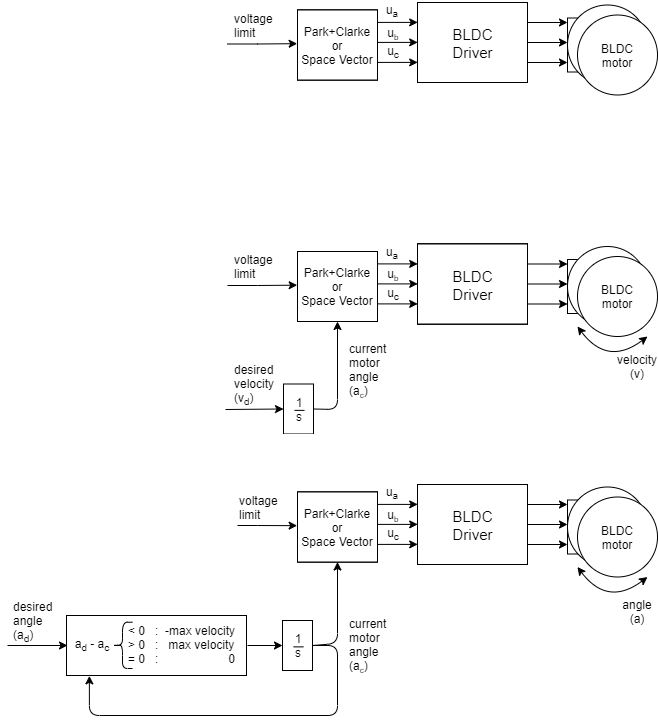
简单的FOC库让您可以选择使用 2 种不同的开环控制策略:
索引搜索使用也使用开环位置控制,但有一些附加参数,请参阅索引搜索
// MotionControlType::velocity_openloop    - velocity open-loop control
// MotionControlType::angle_openloop       - position open-loop control
motor.controller = MotionControlType::angle_openloop;
速度开环控制
该控制回路允许您在不使用位置传感器的情况下以所需的速度旋转 BLDC 电机。此模式通过以下方式启用:
// set velocity control open-loop mode
motor.controller = MotionControlType::velocity_openloop;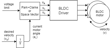
?
您可以通过运行motion_control/openloop_motor_control/文件夹中的示例来测试此算法。
这种控制算法非常简单。用户可以设置它想要达到的目标速度v?d,算法会及时对其进行积分,以找出它需要设置到电机a?c的角度是多少才能实现它。然后将motor.voltage_limit在a?c使用SinePWM或SpaceVectorPWM调制的方向上施加最大允许电压。
这是计算下一个要设置到电机的角度的简化版本:
next_angle = past_angle + target_velocity*d_time;您需要知道为电机设置的角度的target_velocity、采样时间d_time和过去值past_angle。
配置
// choose FOC modulation (optional) - default SinePWM
motor.foc_modulation = FOCModulationType::SpaceVectorPWM;

// limiting voltage
motor.voltage_limit = 3;   // Volts
// or current  - if phase resistance provided
motor.current_limit = 0.5 // Amps这种类型的运动控制效率非常低,因此尽量不要使用高值motor.voltage_limit。我们建议您为电机等级提供phase_resistance值并设置motor.current_limit电压限制。这个电流可能会被超过,但至少你会知道你的电机正在消耗的近似电流。您可以通过检查电机电阻phase_resistance和评估来计算电机将产生的电流:
voltage_limit = current_limit * phase_resistance; // Amps此外,如果您的应用需要这种行为,您可以实时更改电压/电流限制。
速度开环控制示例
以下是具有完整配置的速度开环控制的一个基本示例。程序会设置目标速度2 RAD/s并维护它,用户可以通过串口终端改变目标速度。
// Open loop motor control example
#include <SimpleFOC.h>

// BLDC motor & driver instance
// BLDCMotor( pp number , phase resistance)
BLDCMotor motor = BLDCMotor(11 , 12.5);
BLDCDriver3PWM driver = BLDCDriver3PWM(9, 5, 6, 8);

//target variable
float target_velocity = 2; // rad/s

// instantiate the commander
Commander command = Commander(Serial);
void doTarget(char* cmd) { command.variable(&target_velocity, cmd); }

void setup() {

  // driver config
  // power supply voltage [V]
  driver.voltage_power_supply = 12;
  driver.init();
  // link the motor and the driver
  motor.linkDriver(&driver);

  // limiting motor current (provided resistance)
  motor.current_limit = 0.5;   // [Amps]

  // open loop control config
  motor.controller = MotionControlType::velocity_openloop;

  // init motor hardware
  motor.init();

  // add target command T
  command.add('T', doTarget, "target velocity");

  Serial.begin(115200);
  Serial.println("Motor ready!");
  Serial.println("Set target velocity [rad/s]");
  _delay(1000);
}

void loop() {

  // open loop velocity movement
  // using motor.current_limit and motor.velocity_limit
  motor.move(target_velocity);

  // user communication
  command.run();
}
位置开环控制
该控制回路允许您在不使用位置传感器的情况下实时将电机移动到所需的角度。此模式通过以下方式启用:
// set position motion control open-loop
motor.controller = MotionControlType::angle_openloop;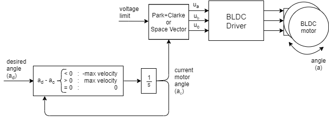
您可以通过运行motion_control/open_loop_motor_control/文件夹中的示例来测试此算法。
这种控制算法非常简单。用户设置它希望达到目标角度一d。该算法仅减去当前角度a?c和所需角度a?d以找到它需要移动的方向,并以可能的最高速度motor.velocity_limit(最大速度)朝该方向移动。要设置该速度,它使用与速度开环控制相同的算法。它及时对速度进行积分,以找出它需要为电机设置的角度a?c以实现它。然后将使用或motor.voltage_limit在a?c的方向上施加最大允许电压SinePWMSpaceVector?调制。
配置
// choose FOC modulation (optional)
motor.foc_modulation = FOCModulationType::SpaceVectorPWM;

//  maximal velocity of the position control
// default 20
motor.velocity_limit = 20;

// limiting voltage
motor.voltage_limit = 3;   // Volts
// or current  - if phase resistance provided
motor.current_limit = 0.5 // Amps这种类型的运动控制效率非常低,因此尽量不要使用高值motor.voltage_limit。我们建议您为电机等级提供phase_resistance值并设置motor.current_limit电压限制。这个电流可能会被超过,但至少你会知道你的电机正在消耗的近似电流。您可以通过检查电机电阻phase_resistance和评估来计算电机将产生的电流:
voltage_limit = current_limit * phase_resistance; // Amps最大速度motor.velocity_limit值将决定您的电机在位置之间的运行速度。值越高,转换越快。但是由于我们在开环中转动电机,我们将无法知道电机是否可以跟随速度。因此,请确保velocity_limit输入您的电机可实现的值。还要注意,要获得更高的速度和更大的保持扭矩,您还需要增加motor.voltage_limit或motor.current_limit变量。
此外,如果您的应用需要这种行为,您可以实时更改电压限制motor.voltage_limit(?motor.current_limit) 和转换速度motor.velocity_limit。
位置开环控制示例
以下是具有完整配置的速度开环控制的一个基本示例。程序会对其目标位置进行设置0 RAD和维护,用户可以通过串口终端更改目标位置。
// Open loop motor control example
#include <SimpleFOC.h>

// BLDC motor & driver instance
BLDCMotor motor = BLDCMotor(11);
BLDCDriver3PWM driver = BLDCDriver3PWM(9, 5, 6, 8);

//target variable
float target_position = 0;

// instantiate the commander
Commander command = Commander(Serial);
void doTarget(char* cmd) { command.variable(&target_position, cmd); }

void setup() {

  // driver config
  // power supply voltage [V]
  driver.voltage_power_supply = 12;
  driver.init();
  // link the motor and the driver
  motor.linkDriver(&driver);

  // limiting motor movements
  motor.voltage_limit = 3;   // [V]
  motor.velocity_limit = 5; // [rad/s] cca 50rpm
  // open loop control config
  motor.controller = MotionControlType::angle_openloop;

  // init motor hardware
  motor.init();

  // add target command T
  command.add('T', doTarget, "target angle");

  Serial.begin(115200);
  Serial.println("Motor ready!");
  Serial.println("Set target position [rad]");
  _delay(1000);
}

void loop() {
  // open  loop angle movements
  // using motor.voltage_limit and motor.velocity_limit
  motor.move(target_position);

  // user communication
  command.run();
}
索引搜索例程
仅当Encoder类的构造函数已提供indexpin 时,才会执行查找编码器索引。通过设置电机的恒定速度直到它到达索引销来执行搜索。要设置所需的搜索速度,请更改参数:
// index search velocity - default 1rad/s
motor.velocity_index_search = 2;索引搜索在motor.initFOC()函数中执行。
该速度控制回路的实现与速度开环完全相同,唯一的区别是设置到电机的电压不是motor.volatge_limit(或motor.curren_limit*motor.phase_resistance)而是motor.voltage_sensor_align。
使用索引搜索的代码示例
这是一个运动控制程序的例子,它使用编码器作为位置传感器,特别是带有index信号的编码器。索引搜索速度设置为3 RAD/s:
// index search velocity [rad/s]
motor.velocity_index_search = 3;motor.initFOC()通过索引搜索将电机和位置传感器对齐后。电机将开始以角速度旋转2 RAD/s并保持该值。
#include <SimpleFOC.h>

// motor instance
BLDCMotor motor = BLDCMotor(11);
// driver instance
BLDCDriver3PWM driver = BLDCDriver3PWM(9, 10, 11, 8);

// encoder instance
Encoder encoder = Encoder(2, 3, 500, A0);
// channel A and B callbacks
void doA(){encoder.handleA();}
void doB(){encoder.handleB();}
void doIndex(){encoder.handleIndex();}


void setup() {

  // initialize encoder sensor hardware
  encoder.init();
  encoder.enableInterrupts(doA, doB,doIndex);

  // link the motor to the sensor
  motor.linkSensor(&encoder);

  // driver config
  driver.init();
  motor.linkDriver(&driver);

  // index search velocity [rad/s]
  motor.velocity_index_search = 3; // rad/s
  motor.voltage_sensor_align = 4; // Volts

  // set motion control loop to be used
  motor.controller = MotionControlType::velocity;

  // controller configuration
  // default parameters in defaults.h

  // velocity PI controller parameters
  motor.PID_velocity.P = 0.2;
  motor.PID_velocity.I = 20;
  // default voltage_power_supply
  motor.voltage_limit = 6;
  // jerk control using voltage voltage ramp
  // default value is 300 volts per sec  ~ 0.3V per millisecond
  motor.PID_velocity.output_ramp = 1000;

  // velocity low pass filtering time constant
  motor.LPF_velocity.Tf = 0.01;


  // use monitoring with serial
  Serial.begin(115200);
  // comment out if not needed
  motor.useMonitoring(Serial);

  // initialize motor
  motor.init();
  // align encoder and start FOC
  motor.initFOC();


  Serial.println("Motor ready.");
  _delay(1000);
}

// angle set point variable
float target_velocity = 2;

void loop() {
  // main FOC algorithm function
  motor.loopFOC();

  // Motion control function
  motor.move(target_velocity);

}
软件翻译的不是很恰当,以后再慢慢更改.