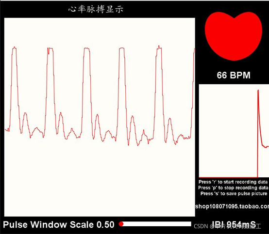
基于STM32 Pulse sensor心率模块测试 上位机显示心跳数据
一. 实现功能
上电后上位机显示心跳脉冲线条和心率数据,如图

二. 硬件清单
- Pulse sensor心率模块
- STM32F103C8T6/STC89C52RC(此单片机无AD故没法使用)
- SWD或JLINK仿真器(直接用CH340串口模块烧录也行,不过注意配置BOOT)
- 杜邦线若干
三. 资料清单
程序代码

文档资料

四. 模块简介
1.基本参数
详情看这两份文档就好

2.引脚说明

五. 接线
基于STM32 +模块接线
模块--------- ------------------------ STM32
VCC-----------------------------------3.3V
GND-----------------------------------GND
S----------------- ---------------- - GPIOA_0(AD1通道0)
六.代码说明
以下以32代码为例, OLED相关链接:
1. AD1通道0配置
/**
  * @brief  ADC GPIO 初始化
  * @param  无
  * @retval 无
  */
static void ADCx_GPIO_Config(void)
{
	GPIO_InitTypeDef GPIO_InitStructure;

	// 打开 ADC IO端口时钟
	ADC_GPIO_APBxClock_FUN ( ADC_GPIO_CLK, ENABLE );

	// 配置 ADC IO 引脚模式
	// 必须为模拟输入
	GPIO_InitStructure.GPIO_Pin = ADC_PIN;
	GPIO_InitStructure.GPIO_Mode = GPIO_Mode_AIN;

	// 初始化 ADC IO
	GPIO_Init(ADC_PORT, &GPIO_InitStructure);
}
/**
  * @brief  配置ADC工作模式
  * @param  无
  * @retval 无
  */
static void ADCx_Mode_Config(void)
{
	ADC_InitTypeDef ADC_InitStructure;

	// 打开ADC时钟
	ADC_APBxClock_FUN ( ADC_CLK, ENABLE );

	// ADC 模式配置
	// 只使用一个ADC,属于独立模式
	ADC_InitStructure.ADC_Mode = ADC_Mode_Independent;

	// 禁止扫描模式,多通道才要,单通道不需要
	ADC_InitStructure.ADC_ScanConvMode = DISABLE ;

	// 连续转换模式
	ADC_InitStructure.ADC_ContinuousConvMode = ENABLE;

	// 不用外部触发转换,软件开启即可
	ADC_InitStructure.ADC_ExternalTrigConv = ADC_ExternalTrigConv_None;

	// 转换结果右对齐
	ADC_InitStructure.ADC_DataAlign = ADC_DataAlign_Right;

	// 转换通道1个
	ADC_InitStructure.ADC_NbrOfChannel = 1;

	// 初始化ADC
	ADC_Init(ADCx, &ADC_InitStructure);

	// 配置ADC时钟为PCLK2的8分频,即9MHz
	RCC_ADCCLKConfig(RCC_PCLK2_Div8);

	// 配置 ADC 通道转换顺序和采样时间
	ADC_RegularChannelConfig(ADCx, ADC_CHANNEL, 1,
	                         ADC_SampleTime_55Cycles5);

//	// ADC 转换结束产生中断,在中断服务程序中读取转换值
//	ADC_ITConfig(ADCx, ADC_IT_EOC, ENABLE);

	// 开启ADC ,并开始转换
	ADC_Cmd(ADCx, ENABLE);

	// 初始化ADC 校准寄存器
	ADC_ResetCalibration(ADCx);
	// 等待校准寄存器初始化完成
	while(ADC_GetResetCalibrationStatus(ADCx));

	// ADC开始校准
	ADC_StartCalibration(ADCx);
	// 等待校准完成
	while(ADC_GetCalibrationStatus(ADCx));

	// 由于没有采用外部触发,所以使用软件触发ADC转换
	ADC_SoftwareStartConvCmd(ADCx, ENABLE);
}
2. 定时器TIM3初始化函数
// 中断优先级配置
static void GENERAL_TIM_NVIC_Config(void)
{
    NVIC_InitTypeDef NVIC_InitStructure;
    // 设置中断组为0
    NVIC_PriorityGroupConfig(NVIC_PriorityGroup_0);
		// 设置中断来源
    NVIC_InitStructure.NVIC_IRQChannel = GENERAL_TIM_IRQ ;
		// 设置主优先级为 0
    NVIC_InitStructure.NVIC_IRQChannelPreemptionPriority = 0;
	  // 设置抢占优先级为3
    NVIC_InitStructure.NVIC_IRQChannelSubPriority = 3;
    NVIC_InitStructure.NVIC_IRQChannelCmd = ENABLE;
    NVIC_Init(&NVIC_InitStructure);
}

///*
// * 注意:TIM_TimeBaseInitTypeDef结构体里面有5个成员,TIM6和TIM7的寄存器里面只有
// * TIM_Prescaler和TIM_Period,所以使用TIM6和TIM7的时候只需初始化这两个成员即可,
// * 另外三个成员是通用定时器和高级定时器才有.
// *-----------------------------------------------------------------------------
// *typedef struct
// *{ TIM_Prescaler            都有
// *	TIM_CounterMode			     TIMx,x[6,7]没有,其他都有
// *  TIM_Period               都有
// *  TIM_ClockDivision        TIMx,x[6,7]没有,其他都有
// *  TIM_RepetitionCounter    TIMx,x[1,8,15,16,17]才有
// *}TIM_TimeBaseInitTypeDef;
// *-----------------------------------------------------------------------------
// */
static void GENERAL_TIM_Mode_Config(void)
{
	TIM_TimeBaseInitTypeDef  TIM_TimeBaseStructure;
		// 开启定时器时钟,即内部时钟CK_INT=72M
    GENERAL_TIM_APBxClock_FUN(GENERAL_TIM_CLK, ENABLE);
		// 自动重装载寄存器的值,累计TIM_Period+1个频率后产生一个更新或者中断
    TIM_TimeBaseStructure.TIM_Period=GENERAL_TIM_Period;
	  // 时钟预分频数
    TIM_TimeBaseStructure.TIM_Prescaler= GENERAL_TIM_Prescaler;
		// 时钟分频因子 ,没用到不用管
    TIM_TimeBaseStructure.TIM_ClockDivision=TIM_CKD_DIV1;
		// 计数器计数模式,设置为向上计数
    TIM_TimeBaseStructure.TIM_CounterMode=TIM_CounterMode_Up;
		// 重复计数器的值,没用到不用管
		TIM_TimeBaseStructure.TIM_RepetitionCounter=0;
	  // 初始化定时器
    TIM_TimeBaseInit(GENERAL_TIM, &TIM_TimeBaseStructure);

		// 清除计数器中断标志位
    TIM_ClearFlag(GENERAL_TIM, TIM_FLAG_Update);

		// 开启计数器中断
    TIM_ITConfig(GENERAL_TIM,TIM_IT_Update,ENABLE);

		// 使能计数器
    TIM_Cmd(GENERAL_TIM, ENABLE);
}
3. 获取AD值并滤波,心率计算函数
注:,此函数放在定时器中断中
void GENERAL_TIM_IRQHandler()
{
		unsigned int runningTotal;
		int i;
			if (ADC_GetFlagStatus(ADCx,ADC_FLAG_EOC)==SET)
			{
				// 读取ADC的转换值
				Signal = ADC_GetConversionValue(ADCx)>>2;
//				printf("AD:%d\r\n",ADC_ConvertedValue);
						//	Signal=ADC_ConvertedValue;					 // read the Pulse Senso
			}
			ADC_ClearFlag(ADCx,ADC_FLAG_EOC);

			sampleCounter += 2;                         // keep track of the time in mS with this variable
			Num = sampleCounter - lastBeatTime;       // monitor the time since the last beat to avoid noise


		//  find the peak and trough of the pulse wave
			if(Signal < thresh && Num > (IBI/5)*3)
			{       // avoid dichrotic noise by waiting 3/5 of last IBI
					if (Signal < T)
					{                        // T is the trough
						T = Signal;                         // keep track of lowest point in pulse wave
					}
			}

			if(Signal > thresh && Signal > P)
			{          // thresh condition helps avoid noise
				P = Signal;                             // P is the peak
			}                                        // keep track of highest point in pulse wave

  //  NOW IT'S TIME TO LOOK FOR THE HEART BEAT
  // signal surges up in value every time there is a pulse
  if (Num > 250)
	{                                   // avoid high frequency noise
			if ( (Signal > thresh) && (Pulse == false) && (Num > (IBI/5)*3) )
			{
					Pulse = true;                               // set the Pulse flag when we think there is a pulse

					IBI = sampleCounter - lastBeatTime;         // measure time between beats in mS
					lastBeatTime = sampleCounter;               // keep track of time for next pulse

					if(secondBeat)
					{                        // if this is the second beat, if secondBeat == TRUE
							secondBeat = false;                  // clear secondBeat flag
							for( i=0; i<=9; i++)
							{             // seed the running total to get a realisitic BPM at startup
								rate[i] = IBI;
							}
					}

					if(firstBeat)
					{                         // if it's the first time we found a beat, if firstBeat == TRUE
						firstBeat = false;                   // clear firstBeat flag
						secondBeat = true;                   // set the second beat flag
		 //       sei();                               // enable interrupts again
						return;                              // IBI value is unreliable so discard it
					}


      // keep a running total of the last 10 IBI values
					runningTotal = 0;                  // clear the runningTotal variable

					for( i=0; i<=8; i++)
					{                // shift data in the rate array
						rate[i] = rate[i+1];                  // and drop the oldest IBI value
						runningTotal += rate[i];              // add up the 9 oldest IBI values
					}

					rate[9] = IBI;                          // add the latest IBI to the rate array
					runningTotal += rate[9];                // add the latest IBI to runningTotal
					runningTotal /= 10;                     // average the last 10 IBI values
					BPM = 60000/runningTotal;               // how many beats can fit into a minute? that's BPM!
					QS = true;                              // set Quantified Self flag
      // QS FLAG IS NOT CLEARED INSIDE THIS ISR
			}


  if (Signal < thresh && Pulse == true)
	{   // when the values are going down, the beat is over

			Pulse = false;                         // reset the Pulse flag so we can do it again
			amp = P - T;                           // get amplitude of the pulse wave
			thresh = amp/2 + T;                    // set thresh at 50% of the amplitude
			P = thresh;                            // reset these for next time
			T = thresh;
  }

  if (Num > 2500)
	{                           // if 2.5 seconds go by without a beat
			thresh = 512;                          // set thresh default
			P = 512;                               // set P default
			T = 512;                               // set T default
			lastBeatTime = sampleCounter;          // bring the lastBeatTime up to date
			firstBeat = true;                      // set these to avoid noise
			secondBeat = false;                    // when we get the heartbeat back
  }

	}
	TIM_ClearITPendingBit(GENERAL_TIM , TIM_FLAG_Update);
}
4. 主函数
/**
  * @brief  主函数
  * @param  无
  * @retval 无
  */
int main(void)
{

	// ADC 初始化
	USART_Config();
	GENERAL_TIM_Init();
	ADCx_Init();
	DelayInit();

//	OLED_Init();
//	OLED_Clear();
	while (1)
	{

			sendDataToProcessing('S', Signal);     // send Processing the raw Pulse Sensor data
			if (QS == true)
			{
					sendDataToProcessing('B',BPM);   // send heart rate with a 'B' prefix
					sendDataToProcessing('Q',IBI);   // send time between beats with a 'Q' prefix
					QS = false;                      // reset the Quantified Self flag for next time
			}
			DelayMs(20);
	}
}
七.资料获取
加群私聊群主可免费获得,也可加群学习交流 群号:1041406448。