1. 概述
NXP官方提供了AUTOSAR OS代码,并且可以用EB进行配置,但官方的例程不能直接适用于Keil,本文就来介绍下如何在Keil上编译官方的AUTOSAR OS源码。
之前我们已经介绍过如何在Keil上编译S32系列的MCAL,需要的朋友可以翻一下我之前的文章,本文默认在Keil上已经可以编译调试S32的MCAL(只需要Port和Dio这俩基础模块)。
2. AUTOSAR OS的安装
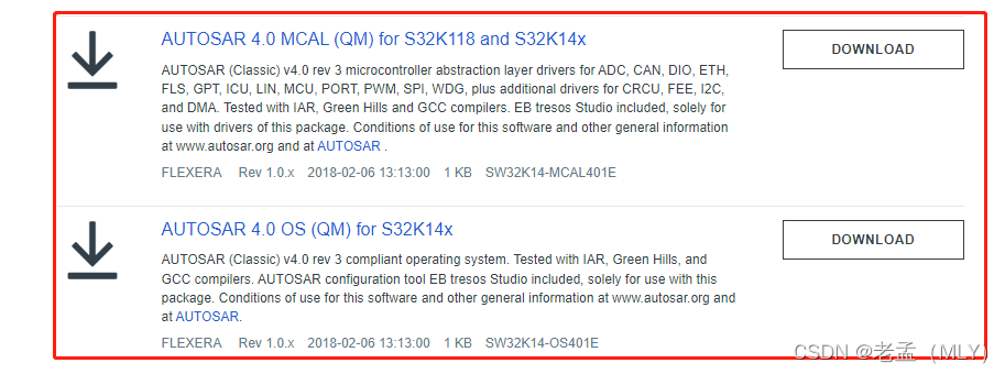
可以从下面的连接下载NXP提供的AUTOSAR OS,如果要结合MCAL一起用的话,也要同时下载相同AUTOSAR版本的MCAL。下载的时候注意同时下载license文件,安装过程比较简单,不展开讲了。
3. 用EB生成配置代码
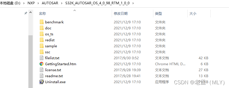
安装完成后,可以看到安装路径下有以下文件夹,其中doc里有各种使用手册,sample是测试例程,ssc中就是源码:
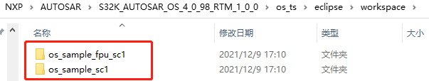
在下面的路径下有两个EB测试demo工程:
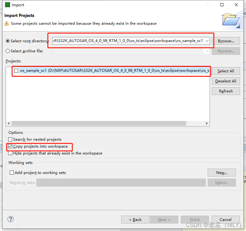
我们打开EB,点击import,选择上面其中的一个工程文件夹(我用的是下面那个),即可导入测试工程:
测试工程导入后如下图所示,我们可以看到工程中已经配置了一些Task、Alarm、Counter等:
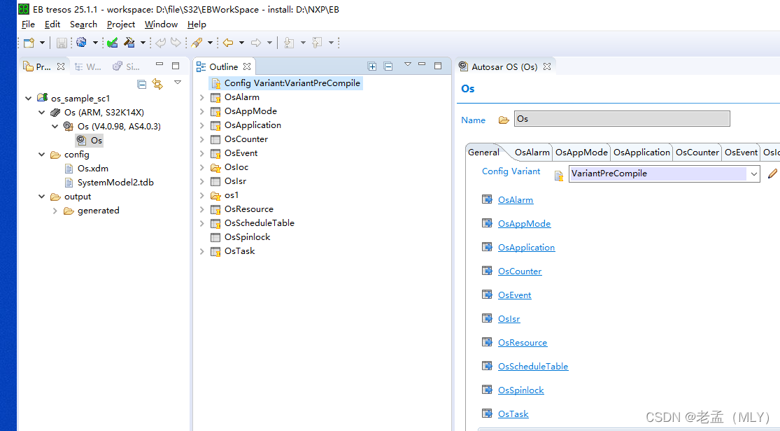
不需要修改任何配置,直接点击生成配置代码即可生成代码,生成的代码在EB工程文件夹下:
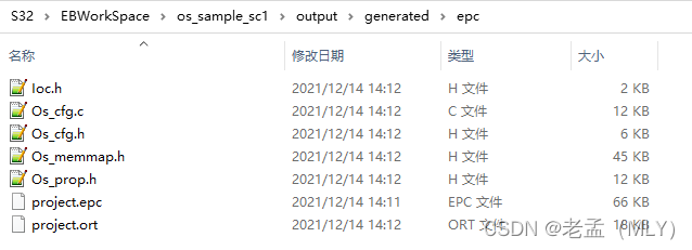
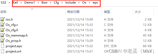
把生成的配置代码拷贝到Keil工程文件夹下,放到哪都行,下面是我放的路径:
4. 拷贝源码
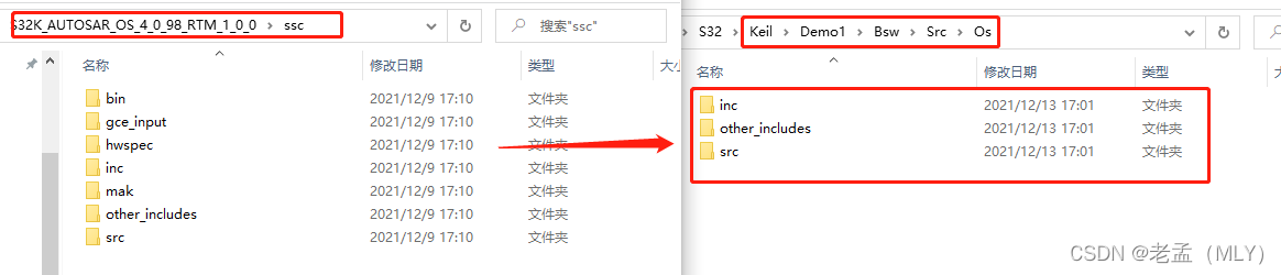
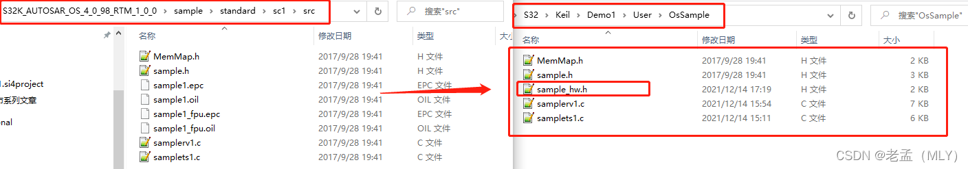
首先把OS的源码拷到Keil的工程文件夹下:
再拷贝测试例程的代码,注意有个头文件在sample的另一个include文件夹下:
5. 在Keil工程中添加源码和头文件路径
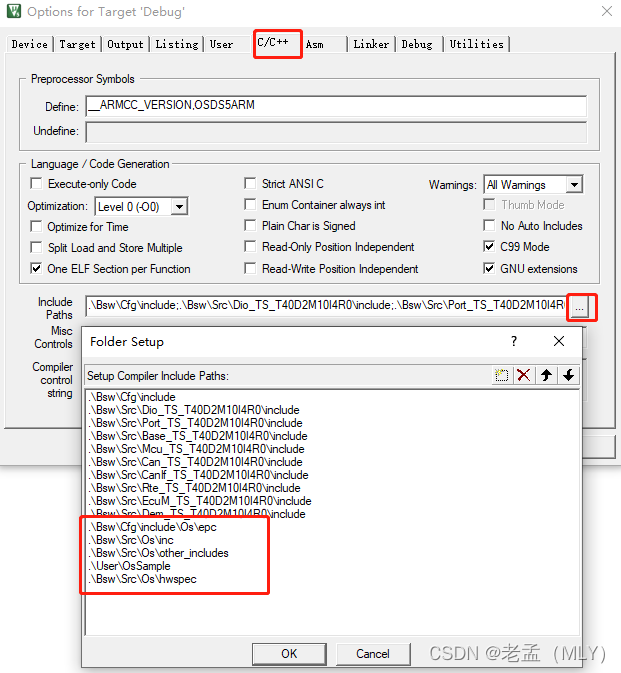
在Keil的工程中,把配置代码、源码和测试例程中所有的头文件路径添加到如下位置:
然后配置Keil源文件,把所有的.c文件都添加到工程中:
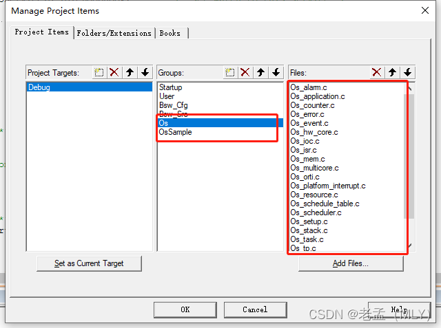
需要注意的是,测试例程中包含了main函数,所以我们要把之前的main.c文件从工程中移除。
6. Keil工程配置
如果是用的我们之前测试MCAL的Keil工程,在配置中有一个定义是控制不使用AUTOSAR OS的,如下图所示:
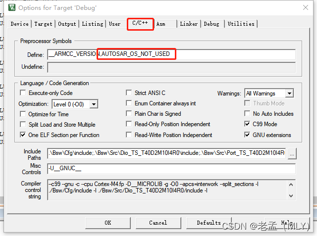
现在我们要把这个给去掉,添加另一个配置定义:
OSDS5ARM
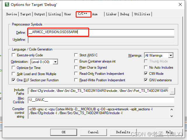
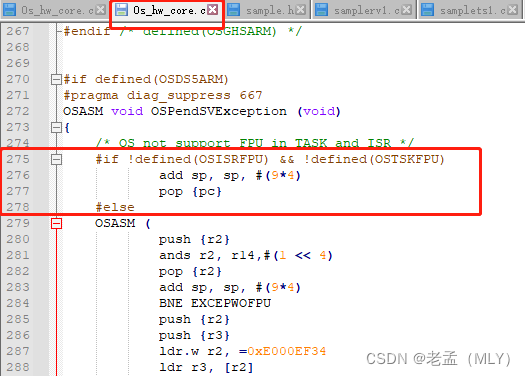
这个定义是选择使用哪个编译器,因为源码中没有定义Keil的MDK编译器,我们暂且先选择这个选项,实测需要修改的地方不多,只有下面一处汇编需要修改:
下图中的位置:

去掉OSASM和括号,修改为:
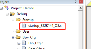
7. 修改启动文件
官方没有提供MDK编译器的启动代码(.s),我们之前测试MCAL的启动代码不能正常运行OS,需要替换为下面链接中的启动代码:
链接:https://pan.baidu.com/s/1v5BTNVH7_ZxKSye2zfB0eQ
提取码:y8bi
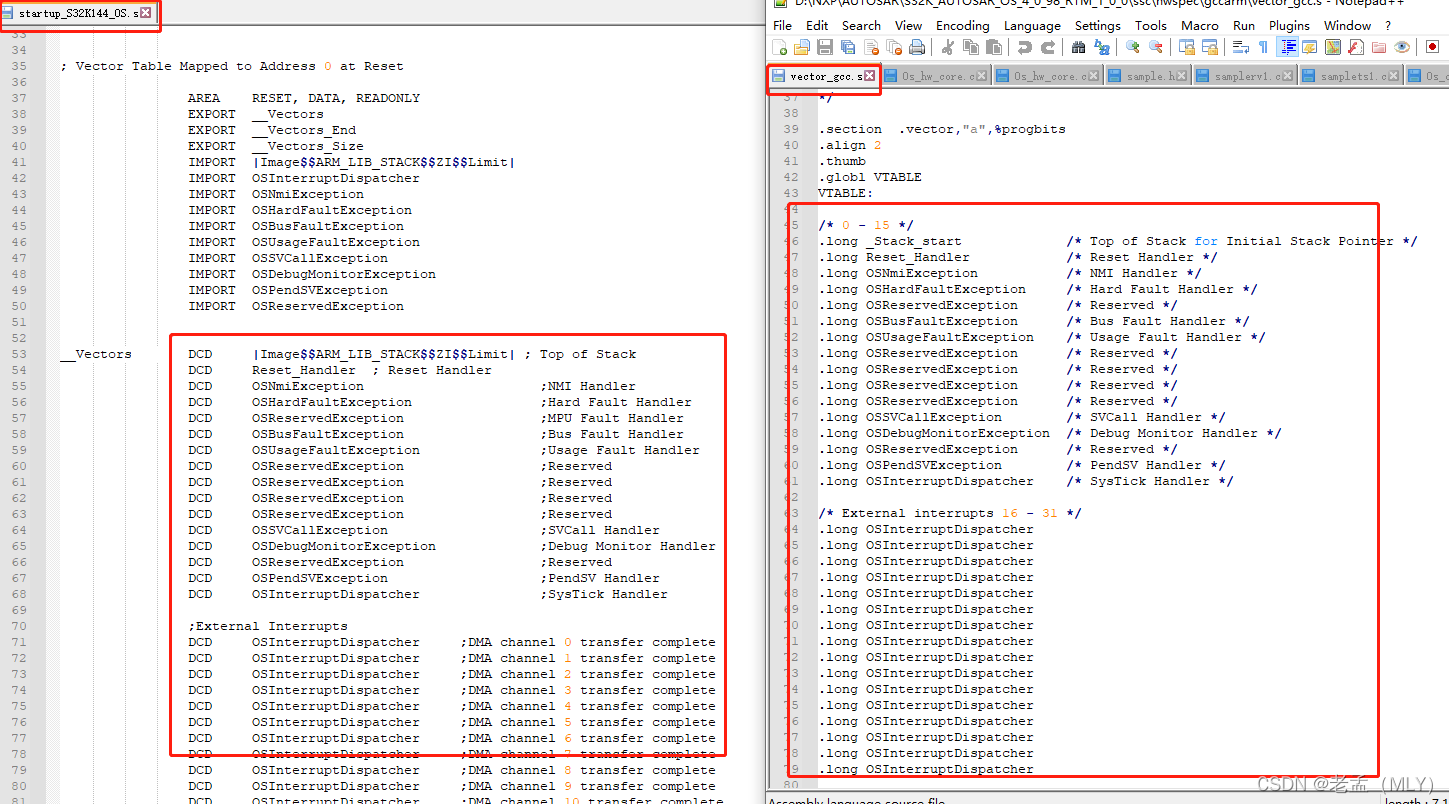
这个启动代码中修改了中断向量表,官方提供的其它编译器的中断向量表在下面的路径下:
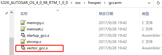
我对照这个修改了之前启动文件的中断向量表:
8. 配置测试例程代码
测试例程的main函数在samplerv1.c中,我们在main函数中添加一些MCAL的初始化:
/***************************************************************************
 * Function:    main
 *
 * Description: inits variables and starts OS
 *
 **************************************************************************/
int main( void )
{
#if defined(OSIARARM)
    extern void SystemInit(void);
    SystemInit();
#endif

    /* Initialize the Mcu driver */
    Mcu_Init(&McuModuleConfiguration_0);

    Mcu_InitClock(McuClockSettingConfig_0);
#if (MCU_NO_PLL == STD_OFF)
    while ( MCU_PLL_LOCKED != Mcu_GetPllStatus() )
    {
        /* Busy wait until the System PLL is locked */
    }

    Mcu_DistributePllClock();
#endif
    Mcu_SetMode(McuModeSettingConf_0);

    /* Initialize all pins using the Port driver */
    Port_Init(&PortConfigSet_0);


    ind = 0;
    repeatCnt = 0;
    repeatCnt1 = 0;
#if defined(OSTSKFPU)
    taskRcv1 = 0.5;
    taskRcv2 = 0.5;
#else
    taskRcv1 = 0;
    taskRcv2 = 0;
#endif
    taskStop = 0;
#if defined(OSTSKFPU)
    taskSnd1 = 0.5;
    taskSnd2 = 0.5;
#else
    taskSnd1 = 0;
    taskSnd2 = 0;
#endif
    taskCnt  = 0;


    StartOS( Mode01 );                            /* jump to OS startup */

    return 0;
}
在sample_hw.h中,需要配置一些硬件接口:
#include "Dio.h"

#define SetGPIO(n)      Dio_WriteChannel(DioConf_DioChannel_DioChannel_LED_GREEN, STD_LOW)
#define ClrGPIO(n)      Dio_WriteChannel(DioConf_DioChannel_DioChannel_LED_GREEN, STD_HIGH)
#define ToogleGPIO(n)   Dio_FlipChannel(DioConf_DioChannel_DioChannel_LED_GREEN);
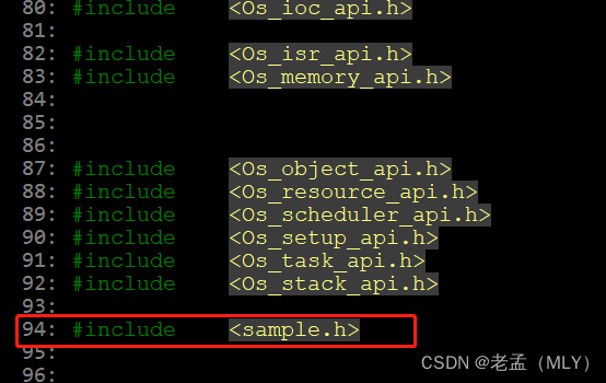
在Os.h中添加sample.h头文件:
9. 编译并测试
完成以上工作后,就可以编译工程了,编译成功后,烧写到开发板中,可以看到上面配置的LED灯闪烁。