??在使用PSIM软件仿真开关电源时,大多数都是模拟电路,纯数字电路的仿真很少。无意间发现了在PSIM 2021版本中有官方的数字控制BUCK电路仿真。电路使用简单C模块编写的代码来控制电路。
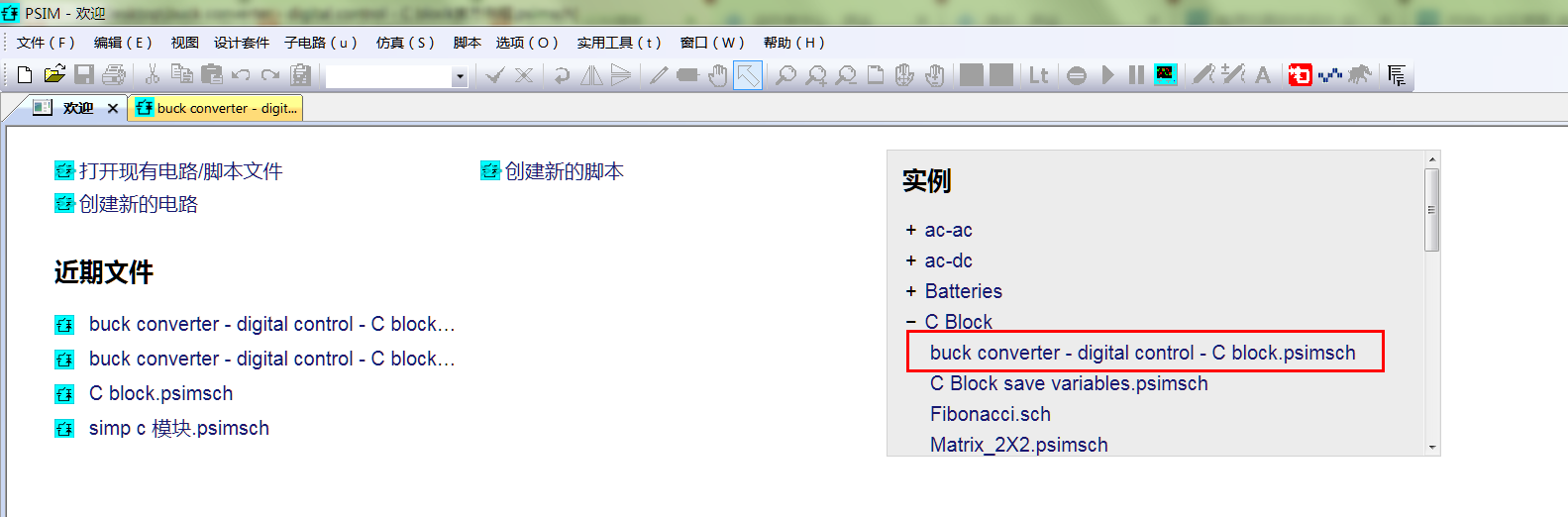
??由于下载的2021版是演示版,不能直接仿真,为了能够彻底的学习,于是将电路图和程序移植到了9.1版本中。现在将电路和代码分享出来。
??2021版官方例程
??由于软件是演示版,有限制,所以不能仿真。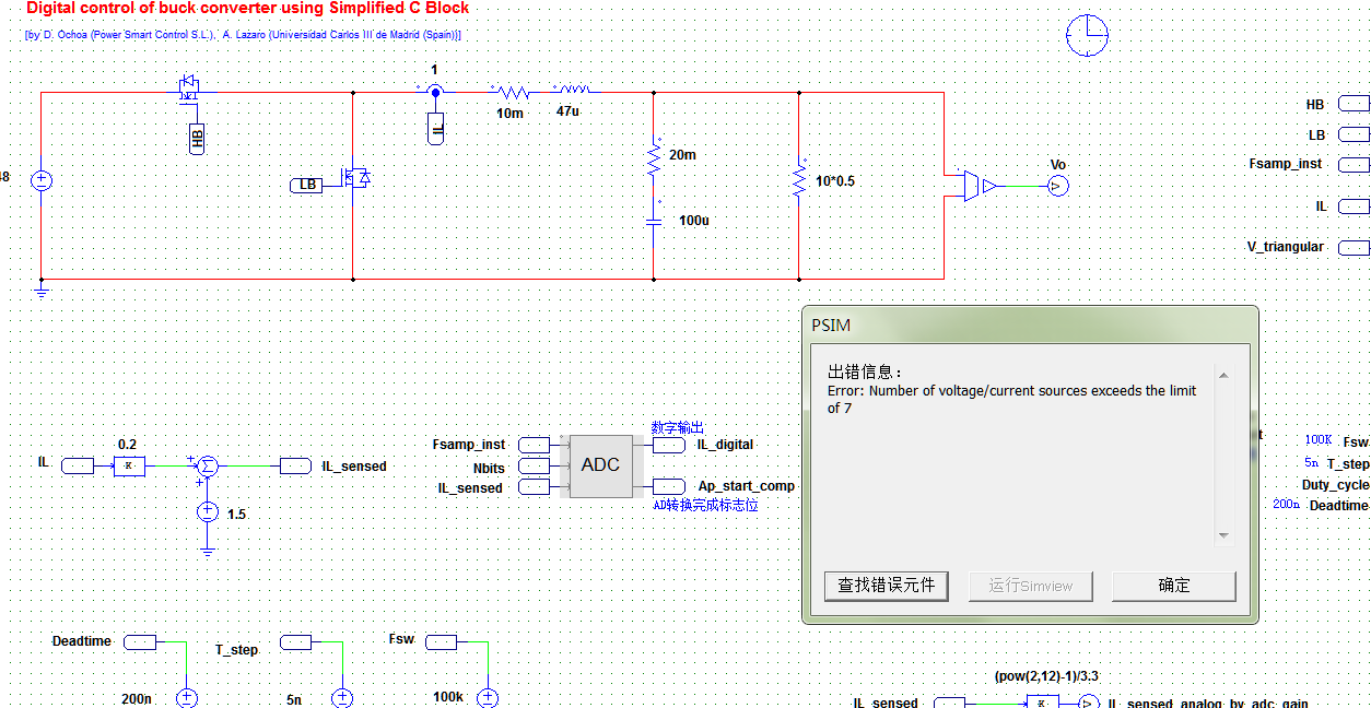
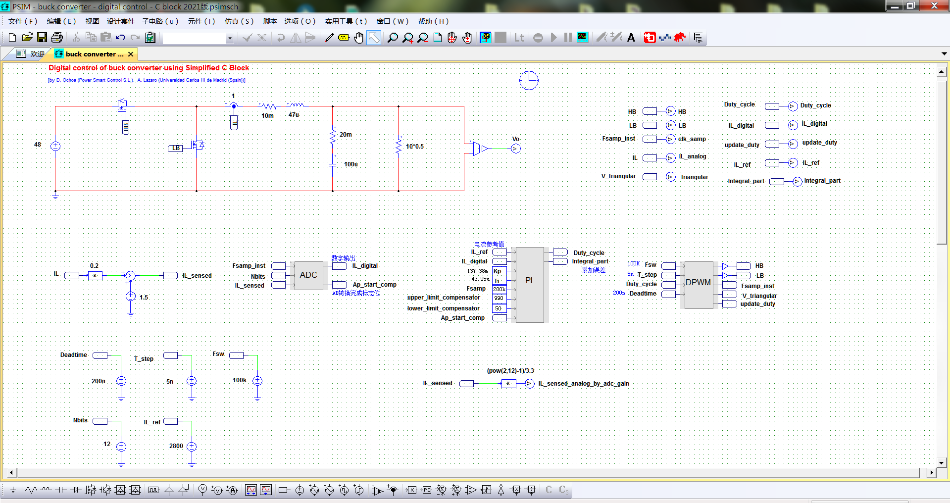
??于是将电路图和代码移植到 PSIM 9.1 版本上
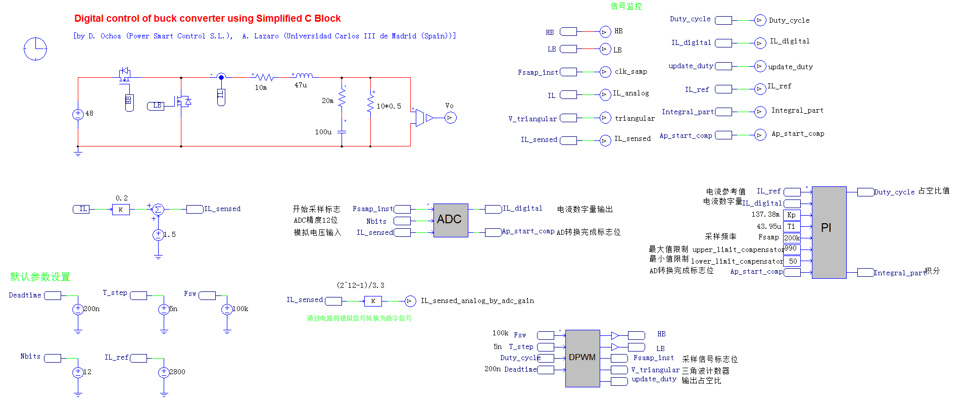
??硬件电路如下:
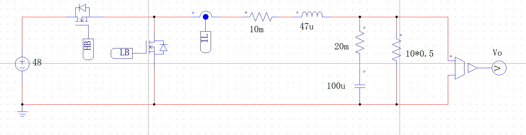
??首先使用电路传感器读取电流值。
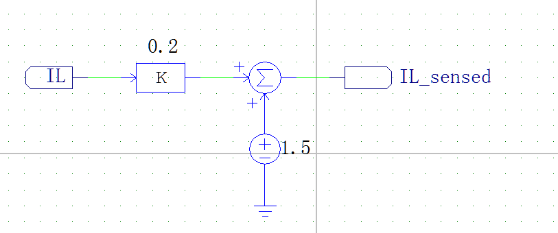
??将采样到的模拟电流值缩小0.2倍然后加上1.5送入到ADC模块中。
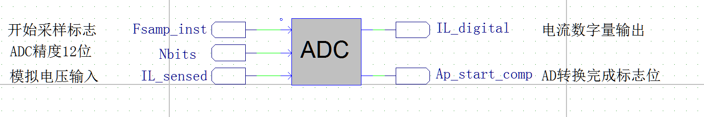
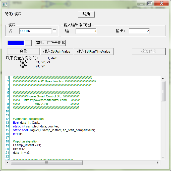
??ADC模块有三路输入信号,两路输出信号。ADC模块是用简化C模块编写代码实现。t它的主要作用是将模拟信号转换为数字信号输出。
/
 ADC Basic function /


/
// Power Smart Control S.L. //
/      https://powersmartcontrol.com/      ///
/                    May 2020                              ///
///


//Variables declaration
float data_in, Gadc;
static int sampled_data, counter;
static bool Flag =1, Fsamp_instant, ap_start_compensator;
int Bits;

//Input assignation
Fsamp_instant = x1;
Bits = x2;
data_in = x3;

//ADC Gain///
/* ADC gain is given by:
 Gadc = ((2^Bits)-1)/(Vmax-Vmin)
Where
Vmax = maximun input voltage of the ADC.
Vmin =  minimum input voltage of the ADC.
Bits =	number of bits of the ADC*/

Gadc = (pow(2,Bits) -1)/3.3;


/Sample and hold, saturation and truncation///
/*As sample_data is an integer therefore
a truncation of the decimal part occurs.*/

if (Fsamp_instant == 1 && Flag ==1){

	if (data_in > 3.3){
		sampled_data = (3.3*Gadc); //Saturation to Vmax
	}

	if (data_in < 0){
		sampled_data = (0*Gadc); //Saturation to Vmin
	}

	if (data_in <= 3.3 && data_in>=0){ //Store the data until the next sampling
		sampled_data = (data_in*Gadc);
	}

Flag = 0;
}


if (Fsamp_instant == 0){
Flag = 1;
ap_start_compensator = 0;
counter = 0;
}


/*A small delay of 2 time steps is considered in order to
guarantee that the data that the compensator will use to
calculate the error is the sample [k]*/

if (Flag == 0){
	counter = counter +1;
}

if (counter > 2){
	ap_start_compensator = 1;
}

//Output assignation
y1 = sampled_data;
y2 = ap_start_compensator;
??ADC模块输出电流的数字量之后,然后在送入PI模块中通过PI公式计算输出占空比的值。
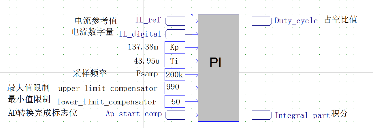
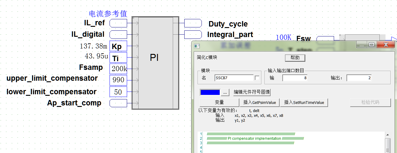
??PI模块有8路输入,2路输出。PI计算时需要的一些常量通过常量模块输入。
/
// PI compensator implementation


/
// Power Smart Control S.L. //
/      https://powersmartcontrol.com/      ///
/                    May 2020                              ///
///


//Variables of the top function
	int IL_ref, IL_sense;
	float Kp, Ti, Fsamp;
	float upper_limit_compensator, lower_limit_compensator;
	static int output;

//Variable Definition
	float A1, A0;
	float e_k, proportional_k, integral_k;
	static float e_k_1, integral_k_1, y_k;

//Variables only for psim simulation
	static bool Flag;
	bool ap_start;

//Input assignation
	Kp = x3;
	Ti = x4;
	Fsamp = x5;
	upper_limit_compensator = x6;
	lower_limit_compensator = x7;
	ap_start = x8;

//Calculate the compensator coefficients of the difference equation
	A0 = Kp;										// 137.38m
	A1 = Kp/(Ti*2*Fsamp);				// 137.38m / ( 43.95u * 2 * 200k) = 7.814562m

//Detect rising edge of the ap_start signal and starts the calculation of the difference equation
if (ap_start == 1 && Flag == 0){
	Flag =1;
	IL_ref = x1;
	IL_sense = x2;

//Calculate the value of the error in the instant [k]
	e_k = IL_ref - IL_sense;		//计算参考值和采样值误差

//Difference equation of the compensator			//  PI 计算
	proportional_k = A0*e_k;				// 误差*Kp
	integral_k = A1*e_k + A1*e_k_1 + integral_k_1;	// Ki * e_k + Ki * e_k-1 + integral_k_1;
	y_k = proportional_k + integral_k;

//Stores sample [K] in variables [K-1] in order to be used in the next sampling instant
	e_k_1 = e_k;
	integral_k_1 = integral_k;

//Limiter at the output of the compensator
	if (y_k >= upper_limit_compensator) {
		y_k = upper_limit_compensator;
	}

	if (y_k <= lower_limit_compensator) {
		y_k = lower_limit_compensator;
	}

	output  =y_k;
}

//Detect falling edge of the ap_start signal
if (ap_start == 0) {
		Flag =0;
}

//Output signal
	y1 = output;
	y2 = integral_k;
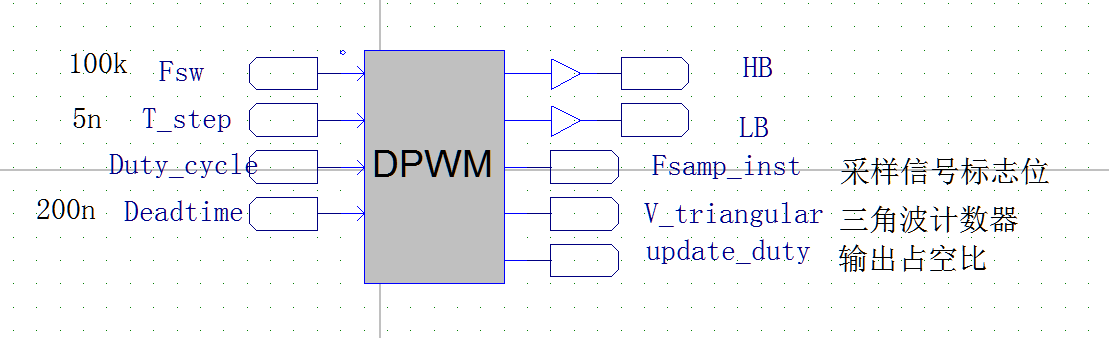
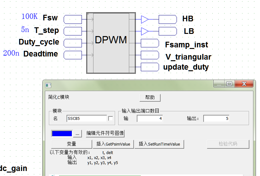
??最后将PI模块输出的占空比控制量送入到DPWM模块中,DPWM模块根据占空比的值输出两路互补的PWM波。
// DPWM with Triangular carrier ///
//

/
// Power Smart Control S.L. //
/      https://powersmartcontrol.com/      ///
/                    May 2020                              ///
///


//Variables declarations
float Fclk_psim, time_step, deadtime;
int Nr, Fsw, digital_deadtime, duty_1, duty_2;
bool samp_inst;
static int counter_trig=0, duty_cycle;
static bool Up=1, Down=0, HB, LB;

//Input assignation
Fsw = x1;
time_step = x2;
deadtime = x4;

//Calculation of the amplitude of the triangular
/* the maximum value of the counter is given by:
				Nr = 0.5*Fclk/Fsw
    Since the psim block is executed every time step
	therefore the frequency of the master clock is:
				Fclk = 1/time_step */

Fclk_psim = 1/time_step;  // 1 / 5ns  200Mhz
Nr = 0.5*Fclk_psim/Fsw; // 0.5 * 200M / 100K = 100M / 100K = 1000

//Updating the duty cycle at the lower vertex of the triangular        //三角波最小值 向上计数
if (counter_trig ==0) {
	Up =1;
	Down =0;
	duty_cycle = x3;
}

//Updating the duty cycle at the upper vertex of the triangular   //三角波最大值 向下计数
if (counter_trig == Nr) {   // 判断计数器是否等于1000
	Up = 0;
	Down =1;
	duty_cycle = x3;
}

//It generates the sampling instant signal   // 输出采样信号 在计数器为 0--4 或者 996-1000时采样
if ((counter_trig >=0 && counter_trig <= 4 && Up ==1) || (counter_trig <= Nr && counter_trig >= Nr-4 && Down ==1 )){
samp_inst = 1;
} else  {
samp_inst = 0;
}

//Triangular Carrier   //生成三角波
if (Up ==1) {
	counter_trig = counter_trig +1;
}

if (Down ==1) {
	counter_trig = counter_trig -1;
}

//Calculations to generate the deadtime
digital_deadtime = deadtime/(2*time_step);  // 200n / ( 2 * 5ns) = 20ns
duty_1 = duty_cycle - digital_deadtime;
duty_2 = duty_cycle + digital_deadtime;

//PWM generation
if (counter_trig >= duty_1){
	HB =0;
} else {
	HB =1;
}

if (duty_2 <= counter_trig){
	LB =1;
} else {
	LB =0;
}

//Output assignation
y1 = HB;
y2 = LB;
y3 = samp_inst;
y4 = counter_trig;
y5 = duty_cycle;
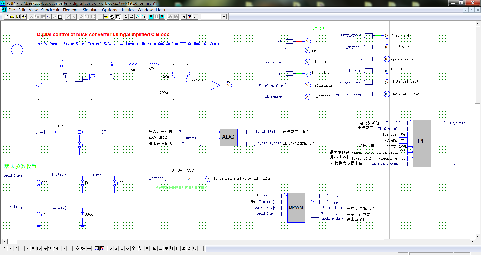
??为了便于验证ADC模块转换的正确性,官方线路中还提供了一个硬件将模拟信号转换为数字信号的电路。

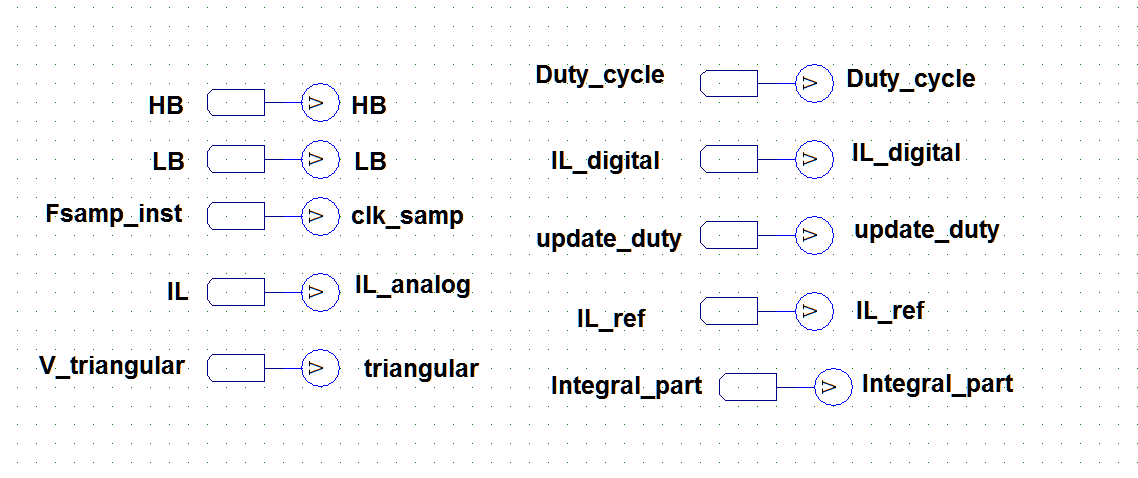
??同时为了便于监控信号,将变量的标签和电压表连接起来,这样就可以直接在波形中观察变量的值。
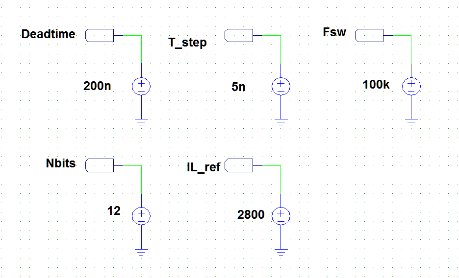
??电路中用到了一些参考值是通过电压源直接输入到模块中的。
??移植到PSIM 9.1 版本中的完整电路如下。
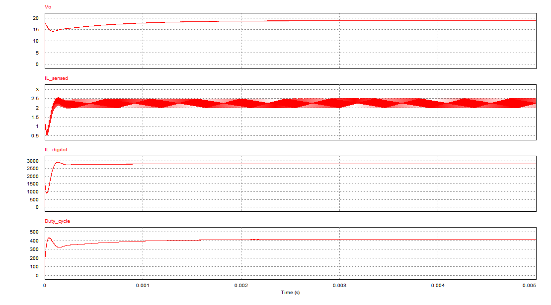
??仿真结果如下
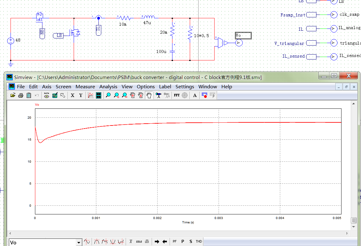
??如果想看其他变量的结果,可以直接在波形中添加。
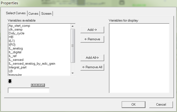
??这里观察输出电流的模拟值,经过ADC模块转换后的数字值,PI模块计算后的占空比值
??官方的代码写的很详细,里面也有很多注释。通过官方的这个例程去理解学习数字电源的仿真,相信大家会有很多收获的。
??仿真文件下载链接:https://download.csdn.net/download/qq_20222919/82906330