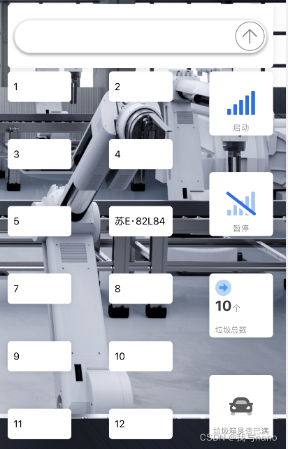
数据上传
前言
最近做项目需要将32的数据上传到手机app,很明显需要用ESP8266,使用串口2遇到了一些问题,就将它记录下来。
一、STM32串口配置

这里是串口一的配置,用的APB2,

串口二用的APB1,这个没有注意,一直不能发数据。使用的时候要注意这个地方。
贴出STM32发送端的代码。
usart.c
#include "sys.h"
#include "usart.h"

//
//è?1?ê1ó?ucos,?ò°üà¨????μ?í·???t?′?é.
#if SYSTEM_SUPPORT_OS
#include "includes.h"					//ucos ê1ó?
#endif

//?óè?ò???′ú??,?§3?printfoˉêy,??2?Dèòa????use MicroLIB
#if 1
#pragma import(__use_no_semihosting)
//±ê×??aDèòaμ??§3?oˉêy
struct __FILE
{
	int handle;

};

FILE __stdout;
//?¨ò?_sys_exit()ò?±ü?aê1ó?°??÷?ú?£ê?
_sys_exit(int x)
{
	x = x;
}
//???¨ò?fputcoˉêy
int fputc(int ch, FILE *f)
{
	while((USART1->SR&0X40)==0);//?-?··¢?í,?±μ?·¢?ííê±?
    USART1->DR = (u8) ch;
	return ch;
}
#endif

#if EN_USART1_RX   //è?1?ê1?üá??óê?
//′??ú1?D??·t??3ìDò
//×¢òa,?áè?USARTx->SR?ü±ü?a?a??????μ?′í?ó
u8 USART_RX_BUF[USART_REC_LEN];     //?óê??o3?,×?′óUSART_REC_LEN??×??ú.

u16 USART_RX_STA=0;       //?óê?×′ì?±ê??

u16 USART2_RX_STA=0;       //?óê?×′ì?±ê??

u8 USART2_RX_BUF[USART2_REC_LEN];     //?óê??o3?,×?′óUSART_REC_LEN??×??ú.

void uart_init(u32 bound){
  //GPIO???úéè??
  GPIO_InitTypeDef GPIO_InitStructure;
	USART_InitTypeDef USART_InitStructure;
	NVIC_InitTypeDef NVIC_InitStructure;

	RCC_APB2PeriphClockCmd(RCC_APB2Periph_USART1|RCC_APB2Periph_GPIOA, ENABLE);	//ê1?üUSART1£?GPIOAê±?ó

	//USART1_TX   GPIOA.9
  GPIO_InitStructure.GPIO_Pin = GPIO_Pin_9; //PA.9
  GPIO_InitStructure.GPIO_Speed = GPIO_Speed_50MHz;
  GPIO_InitStructure.GPIO_Mode = GPIO_Mode_AF_PP;	//?′ó?í?íìê?3?
  GPIO_Init(GPIOA, &GPIO_InitStructure);//3?ê??ˉGPIOA.9

  //USART1_RX	  GPIOA.103?ê??ˉ
  GPIO_InitStructure.GPIO_Pin = GPIO_Pin_10;//PA10
  GPIO_InitStructure.GPIO_Mode = GPIO_Mode_IN_FLOATING;//????ê?è?
  GPIO_Init(GPIOA, &GPIO_InitStructure);//3?ê??ˉGPIOA.10

  //Usart1 NVIC ????
  NVIC_InitStructure.NVIC_IRQChannel = USART1_IRQn;
	NVIC_InitStructure.NVIC_IRQChannelPreemptionPriority=3 ;//?à??ó??è??3
	NVIC_InitStructure.NVIC_IRQChannelSubPriority = 3;		//×óó??è??3
	NVIC_InitStructure.NVIC_IRQChannelCmd = ENABLE;			//IRQí¨μàê1?ü
	NVIC_Init(&NVIC_InitStructure);	//?ù?Y???¨μ?2?êy3?ê??ˉVIC??′??÷

   //USART 3?ê??ˉéè??

	USART_InitStructure.USART_BaudRate = bound;//′??ú2¨ì??ê
	USART_InitStructure.USART_WordLength = USART_WordLength_8b;//×?3¤?a8??êy?Y??ê?
	USART_InitStructure.USART_StopBits = USART_StopBits_1;//ò???í£?1??
	USART_InitStructure.USART_Parity = USART_Parity_No;//?T????D£?é??
	USART_InitStructure.USART_HardwareFlowControl = USART_HardwareFlowControl_None;//?Tó2?têy?Yá÷????
	USART_InitStructure.USART_Mode = USART_Mode_Rx | USART_Mode_Tx;	//ê?·¢?£ê?

  USART_Init(USART1, &USART_InitStructure); //3?ê??ˉ′??ú1
  USART_ITConfig(USART1, USART_IT_RXNE, ENABLE);//?a??′??ú?óêü?D??
  USART_Cmd(USART1, ENABLE);                    //ê1?ü′??ú1

}

void USART1_IRQHandler(void)                	//′??ú1?D??·t??3ìDò
	{
	u8 Res;
#if SYSTEM_SUPPORT_OS 		//è?1?SYSTEM_SUPPORT_OS?a??£??òDèòa?§3?OS.
	OSIntEnter();
#endif
	if(USART_GetITStatus(USART1, USART_IT_RXNE) != RESET)  //?óê??D??(?óê?μ?μ?êy?Y±?D?ê?0x0d 0x0a?á?2)
		{
		Res =USART_ReceiveData(USART1);	//?áè??óê?μ?μ?êy?Y

		if((USART_RX_STA&0x8000)==0)//?óê??′íê3é
			{
			if(USART_RX_STA&0x4000)//?óê?μ?á?0x0d
				{
				if(Res!=0x0a)USART_RX_STA=0;//?óê?′í?ó,??D??aê?
				else USART_RX_STA|=0x8000;	//?óê?íê3éá?
				}
			else //?1??ê?μ?0X0D
				{
				if(Res==0x0d)USART_RX_STA|=0x4000;
				else
					{
					USART_RX_BUF[USART_RX_STA&0X3FFF]=Res ;
					USART_RX_STA++;
					if(USART_RX_STA>(USART_REC_LEN-1))USART_RX_STA=0;//?óê?êy?Y′í?ó,??D??aê??óê?
					}
				}
			}
     }
#if SYSTEM_SUPPORT_OS 	//è?1?SYSTEM_SUPPORT_OS?a??£??òDèòa?§3?OS.
	OSIntExit();
#endif
}

void uart2_init(u32 bound){
	//GPIO???úéè??
 //GPIO???úéè??
	GPIO_InitTypeDef GPIO_InitStructure;
	USART_InitTypeDef USART_InitStructure;
	NVIC_InitTypeDef NVIC_InitStructure;

	RCC_APB2PeriphClockCmd(RCC_APB2Periph_GPIOA, ENABLE);	//ê1?üGPIOAê±?ó
	RCC_APB1PeriphClockCmd(RCC_APB1Periph_USART2,ENABLE);	//ê1?üUSART2

	//USART2_TX   GPIOA.2
	GPIO_InitStructure.GPIO_Pin = GPIO_Pin_2; //PA.2
	GPIO_InitStructure.GPIO_Speed = GPIO_Speed_50MHz;
	GPIO_InitStructure.GPIO_Mode = GPIO_Mode_AF_PP;	//?′ó?í?íìê?3?
	GPIO_Init(GPIOA, &GPIO_InitStructure);//3?ê??ˉGPIOA.2

	//USART1_RX	  GPIOA.33?ê??ˉ
	GPIO_InitStructure.GPIO_Pin = GPIO_Pin_3;//PA3
	GPIO_InitStructure.GPIO_Mode = GPIO_Mode_IN_FLOATING;//????ê?è?
	GPIO_Init(GPIOA, &GPIO_InitStructure);//3?ê??ˉGPIOA.3

	//Usart2 NVIC ????
	NVIC_InitStructure.NVIC_IRQChannel = USART2_IRQn;
	NVIC_InitStructure.NVIC_IRQChannelPreemptionPriority=3 ;//?à??ó??è??3
	NVIC_InitStructure.NVIC_IRQChannelSubPriority = 2;		//×óó??è??3
	NVIC_InitStructure.NVIC_IRQChannelCmd = ENABLE;			//IRQí¨μàê1?ü
	NVIC_Init(&NVIC_InitStructure);	//?ù?Y???¨μ?2?êy3?ê??ˉVIC??′??÷

	//USART 3?ê??ˉéè??

	USART_InitStructure.USART_BaudRate = bound;//′??ú2¨ì??ê
	USART_InitStructure.USART_WordLength = USART_WordLength_8b;//×?3¤?a8??êy?Y??ê?
	USART_InitStructure.USART_StopBits = USART_StopBits_1;//ò???í£?1??
	USART_InitStructure.USART_Parity = USART_Parity_No;//?T????D£?é??
	USART_InitStructure.USART_HardwareFlowControl = USART_HardwareFlowControl_None;//?Tó2?têy?Yá÷????
	USART_InitStructure.USART_Mode = USART_Mode_Rx | USART_Mode_Tx;	//ê?·¢?£ê?
	USART_Init(USART2, &USART_InitStructure); //3?ê??ˉ′??ú2
	USART_ITConfig(USART2, USART_IT_RXNE, ENABLE);//?a??′??ú?óêüoí·¢?í?D??
	USART_Cmd(USART2, ENABLE);

}


void USART2_IRQHandler(void)                    //??2??????
{
   u8 Res,t;
/
	if(USART_GetITStatus(USART2, USART_IT_RXNE) != RESET)  //?óê??D??(?óê?μ?μ?êy?Y±?D?ê?0x0d 0x0a?á?2)
	{
		Res =USART_ReceiveData(USART2);	//?áè??óê?μ?μ?êy?Y
		if((USART2_RX_STA&0x8000)==0)//?óê??′íê3é
			{
			if(USART2_RX_STA&0x4000)//?óê?μ?á?0x0d
				{
				if(Res!=0x0a)USART2_RX_STA=0;//?óê?′í?ó,??D??aê?
				else USART2_RX_STA|=0x8000;	//?óê?íê3éá?
				}
			else //?1??ê?μ?0X0D
				{
				if(Res==0x0d)USART2_RX_STA|=0x4000;
				else
					{
					USART2_RX_BUF[USART2_RX_STA&0X3FFF]=Res ;
					USART2_RX_STA++;
					if(USART2_RX_STA>(USART2_REC_LEN-1))USART2_RX_STA=0;//?óê?êy?Y′í?ó,??D??aê??óê?
					}
				}
			}
}
	}

#endif
usart.h
#ifndef __USART_H
#define __USART_H
#include "stdio.h"
#include "sys.h"

#define USART_REC_LEN  			200  	//?¨ò?×?′ó?óê?×??úêy 200
#define EN_USART1_RX 			1		//ê1?ü£¨1£?/???1£¨0£?′??ú1?óê?
#define USART2_REC_LEN  			200  	//?¨ò?×?′ó?óê?×??úêy 200
#define EN_USART2_RX 			1		//ê1?ü£¨1£?/???1£¨0£?′??ú1?óê?

extern u8  USART_RX_BUF[USART_REC_LEN]; //?óê??o3?,×?′óUSART_REC_LEN??×??ú.??×??ú?a??DD·?
extern u16 USART_RX_STA;         		//?óê?×′ì?±ê??
extern u8  USART2_RX_BUF[USART2_REC_LEN]; //?óê??o3?,×?′óUSART_REC_LEN??×??ú.??×??ú?a??DD·?
extern u16 USART2_RX_STA;
//è?1???′??ú?D???óê?£???2?òa×¢êíò???oê?¨ò?
void uart_init(u32 bound);
void uart2_Init(u32 bound);
void USART2_IRQHandler(void);
#endif
main.c
#include "led.h"
#include "delay.h"
#include "key.h"
#include "sys.h"
#include "usart.h"
u8 *U[20]={"H","Q","W","E","R","T","Y","U"};
 int main(void)
 {
 	u16 t;
	u16 len;
	u16 times=0;
	delay_init();	    	 //?óê±oˉêy3?ê??ˉ
	NVIC_PriorityGroupConfig(NVIC_PriorityGroup_2); //éè??NVIC?D??·?×é2:2???à??ó??è??£?2???ìó|ó??è??
	uart2_init(115200);	 //′??ú3?ê??ˉ?a115200
 	LED_Init();			     //LED???ú3?ê??ˉ
	KEY_Init();          //3?ê??ˉó?°′?üá??óμ?ó2?t?ó?ú
   while(1)
	 {

		 LED1=1;
		 delay_ms(500);
		 LED1=0;
		 delay_ms(500);
	if(KEY0==0)
	{
	USART_SendData(USART2, *U[0]);//?ò′??ú2·¢?íêy?Y
	}
 }
}
二、ESP8266代码
 if (Serial.available() > 0)//串口接收到数据
  {
    incomedate = Serial.read();//获取串口接收到的数据
    if (incomedate == 'H')
    {
       Text6.print("苏E·82L84");
       Serial.print("收到数据");
       Serial.println(incomedate);
    }
 }
ESP8266有效的代码其实就这么多,串口波特率设置对就可以了。贴出完整的代码
#define BLINKER_WIFI

#include <Blinker.h>
#include <DHT.h>·
#include <SoftwareSerial.h>
int incomedate=0;
SoftwareSerial mySerial(2,3);//RX=2,TX=3
char auth[] = "**********"; // blinker app提供的秘钥
char ssid[] = "Mr.Robot";
char pswd[] = "**********";
#define TEXTE_6 "tex-lf6"
BlinkerText Text6(TEXTE_6);
BlinkerButton Button2("btn-wfu");//注意:要和APP组件’数据键名’一致
BlinkerButton Button3("btn-pk8");//注意:要和APP组件’数据键名’一致
BlinkerButton Button1("btn-j1q");//注意:要和APP组件’数据键名’一致
BlinkerButton Button4("btn-tbk");//注意:要和APP组件’数据键名’一致
BlinkerButton Button5("btn-2us");//注意:要和APP组件’数据键名’一致
BlinkerButton Button6("btn-thr");//注意:要和APP组件’数据键名’一致
BlinkerNumber HUMI("num-dax");
BlinkerNumber TEMP("num-2ev");
#define TEXTE_2 "tex-zbf"
BlinkerText Text2(TEXTE_2);
#define TEXTE_5 "tex-cnz"
BlinkerText Text5(TEXTE_5);
#define TEXTE_10 "tex-orn"
BlinkerText Text10(TEXTE_10);
BlinkerNumber chewei("num-xub");
#define LED   4  // 板子上的灯
#define DHTPIN 2     // what digital pin we're connected to
#define DHTTYPE DHT11   // DHT 11
DHT dht(DHTPIN, DHTTYPE);
float humi_read = 0, temp_read = 0;
int i=0,a;
void heartbeat()
{
    HUMI.print(humi_read);
    //反馈湿度数据
    TEMP.print(temp_read);
}
void button2_callback(const String & state)
{
    BLINKER_LOG("get button state: ", state);
    digitalWrite(LED, !digitalRead(LED));

}
void button1_callback(const String & state)
{

  // BLINKER_LOG("get button state: ", state);
    if (state=="on") {
        Serial.println("kai");

    }

}
void button5_callback(const String & state)
{

  // BLINKER_LOG("get button state: ", state);
    if (state=="on") {
        Serial.println("kaimen");

    }

}
void button6_callback(const String & state)
{

  // BLINKER_LOG("get button state: ", state);
    if (state=="on") {
        Serial.println("guanmen");

    }

}
void button4_callback(const String & state)
{

  // BLINKER_LOG("get button state: ", state);
    if (state=="on") {
        Serial.println("kaiqi");

    }

}
void button3_callback(const String & state)
{

  // BLINKER_LOG("get button state: ", state);
    if (state=="on") {
        Serial.println("guan");

    }

}
void dataRead(const String & data)
{
    BLINKER_LOG("Blinker readString: ", data);

    Blinker.vibrate();
    a=12-i;
    chewei.print(a);

   if (Serial.available() > 0)//串口接收到数据
  {
    incomedate = Serial.read();//获取串口接收到的数据
    if (incomedate == 'H')
    {
       Text6.print("苏E·82L84");
       Serial.print("收到数据");
       Serial.println(incomedate);
       ++i;
       a=12-i;
    chewei.print(a);
    }
     if (incomedate == 'Q')
    {
       Text2.print("苏E·42J68");
       ++i;
       a=12-i;
    chewei.print(a);
    }
     if (incomedate == 'W')
    {
       Text5.print("京K·98410");
       ++i;
       a=12-i;
    chewei.print(a);
    }
     if (incomedate == 'E')
    {
       Text10.print("京N·2B945");
        ++i;
       a=12-i;
    chewei.print(a);
    }
     if (incomedate == 'R')
    {
       Text2.print("2");
        --i;
       a=12-i;
    chewei.print(a);
    }
      if (incomedate == 'T')
    {
       Text6.print("6");
      --i;
       a=12-i;
    chewei.print(a);
    }
      if (incomedate == 'Y')
    {
       Text5.print("5");
     --i;
       a=12-i;
    chewei.print(a);
    }
      if (incomedate == 'U')
    {
       Text10.print("10");
        --i;
       a=12-i;
    chewei.print(a);
    }

}
}

void setup()
{
    Serial.begin(115200);
    BLINKER_DEBUG.stream(Serial);
    Button2.attach(button2_callback);
     Button3.attach(button3_callback);
    Button1.attach(button1_callback);
    Button4.attach(button4_callback);
     Button5.attach(button5_callback);
    Button6.attach(button6_callback);
     pinMode(LED, OUTPUT);
    digitalWrite(LED, LOW); // 初始化 led 高电平 ,则灯熄灭状态
    Blinker.begin(auth, ssid, pswd);
    Blinker.attachData(dataRead);
      Blinker.attachHeartbeat(heartbeat);
}

void loop()
{
  int p;
    Blinker.run();
//    read_data();
}
/*void read_data()
{
  float read_h = dht.readHumidity();//湿度
  float read_t = dht.readTemperature();//温度

  humi_read = read_h;
 temp_read = read_t;
}*/
三、现象
按下按键KEY0,发送H

H的ASCII码值是72,可以看到esp接收到了数据。
手机端

总结
其实串口2与串口1并没有太多的区别,只需要注意细节就可以了,手机app端前面提过好多次了,就不介绍了。