So far, we have discussed duty ratio control of PWM converters, in which the converter output
is controlled by direct choice of the duty ratio d(t). We have therefore developed expressions
and small-signal transfer functions that relate the converter waveforms and output voltage to the
duty ratio. This direct duty ratio control is sometimes called voltage mode control, because the
equilibrium output voltage is approximately proportional to the duty cycle in CCM.
? ? ? ?前面已经讨论了PWM变换器的占空比控制,即输出直接受占空比的变化控制。变换器的输出电压和相关波形与占空比的关系,我们已经分析出了相应的数学关系式和小信号传递函数来表达。这种直接占空比控制叫做电压模式控制。因为在CCM的时候,输出电压近似和占空比成比例。
Another control scheme which finds wide application is current programmed control [67, 69,
107, 163–175], in which the converter is controlled by choice of the transistor switch current
peak(is(t)). The control input signal is a current ic(t), and a simple control network switches the
transistor on and off such that the peak transistor current follows ic(t). The transistor duty cycle
d(t) is not directly controlled, but depends on ic(t) as well as on the converter inductor currents,
capacitor voltages, and power input voltage. Converters controlled via current programming
are said to operate in the current-programmed mode (CPM), also known as peak current mode
(PCM) control.
另一种广泛应用的控制模式是电流控制模式,即通过开关管的电流峰值来控制。控制输入信号是
ic(t),通过一个简单的控制器来决定开关管的通断,从而实现峰值电流跟踪ic(t)。此时d(t)不是直接被控制,而是依赖于ic(t),电感电流,电容电压和输入电压。变换器是通过电流曲线规划来控制的。
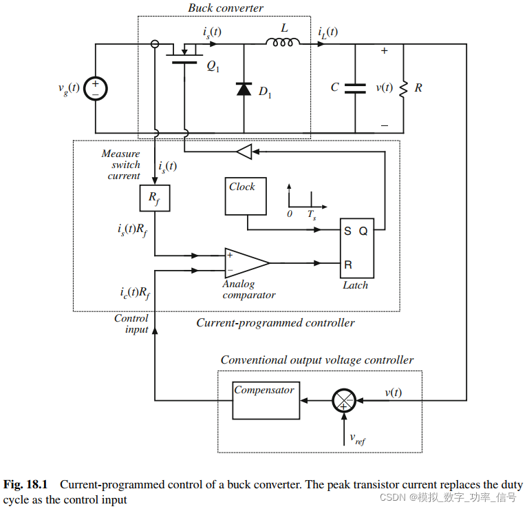
The block diagram of a simple current-programmed controller is illustrated in Fig. 18.1.
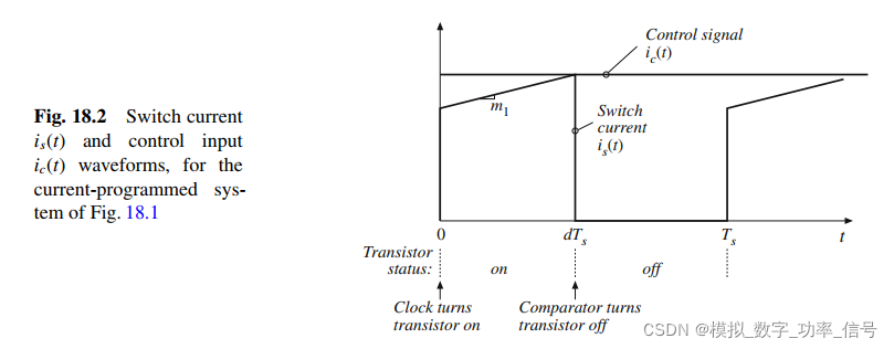
Control signal ic(t) and switch current is(t) waveforms are given in Fig. 18.2. A clock pulse at
the Set input of a latch initiates the switching period, causing the latch output Q to be high
and turning on the transistor switch. While the transistor conducts, its current is(t) is equal to
the inductor current iL(t); this current increases with some positive slope m1 that depends on
the value of inductance and the converter voltages. In more complicated converters, is(t) may
follow the sum of several inductor currents. Eventually, the switch current is(t) becomes equal
to the control signal ic(t). At this point, the controller turns the transistor switch off, and the inductor current decreases for the remainder of the switching period. The controller measures the switch current is(t) with some current sensor circuit, and compares is(t) to ic(t) using an analog comparator. In practice, voltages proportional to is(t) and ic(t) are compared, with constant of proportionality R f . When is(t) ≥ ic(t), the comparator resets the latch, turning the transistor off
for the remainder of the switching period.
图18.1是简化的电流模式控制框图。控制信号额开关电流如图18.2所示。一个时钟控制锁存器的置位控制端,这个时钟就是控制周期Ts。每隔Ts时间间隔到了,都会触发锁存器输出1,进而打开开关管。打开后is(t)就流过电感L,该电流以一定的斜率增加,大小由电感量和电感两端的电压决定。在更复杂的变流器中,is(t)可能流过数个电感。最终is(t)等于控制信号ic(t),此时控制器控制关闭开关管,电感电流在整个关断期间下降。控制器测量开关电流is(t),并且用模拟比较器比较is(t)、ic(t)。实际上代表电流 is(t) and ic(t)的电压通过比较器比较,并且乘以一个固定的系数Rf。当~~~~~~


?As usual, a feedback loop can be constructed for regulation of the output voltage. The output
voltage v(t) is compared to a reference voltage vre f , to generate an error signal. This error signal
is applied to the input of a compensation network, and the output of the compensator drives the
control signal ic(t)R f . To design such a feedback system, we need to model how variations in
the control signal ic(t) and in the line input voltage vg(t) affect the output voltage v(t).
通常,一个反馈环路可以被构建出来,用意控制输出电压。我们需要对控制信号ic(t)和线输入电压vg(t)的变化如何影响输出电压v(t)进行建模。
An advantage of the current-programmed mode is its simpler dynamics. To first order, the
small-signal control-to-output transfer function ? v(s)/?ic(s) contains one less pole than ? v(s)/d?(s).
Actually, the pole is moved to a high frequency, near the converter switching frequency.
Nonetheless, simple robust wide-bandwidth output voltage control can usually be obtained,
without the use of compensator lead networks. It is true that the current-programmed controller
requires a circuit for measurement of the switch current is(t); however, in practice such a circuit
is also required in duty ratio controlled systems, for protection of the transistor against excessive
currents during transients and fault conditions. Current-programmed control makes use of the
available current sensor information during normal operation of the converter, to obtain simpler
system dynamics. Transistor failures due to excessive switch current can then be prevented simply by limiting the maximum value of the control signal ic(t). This ensures that the transistor
will turn off whenever the switch current becomes too large, on a cycle-by-cycle basis.
电流控制模式的一个优点是它的动力学更简单。首先,小信号传递函数?v(s)/?ic(s)比?v(s)/d?(s)少一个极点。实际上,极点移动到接近变换器的开关频率。尽管如此,通常可以获得简单的鲁棒、宽频带输出电压控制,不需要用超前于控制对象的补偿器。确实,电流编程控制器需要一个电路来测量开关电流为(t);然而,在实际中这种电路在直接占空比控制电路中也需要,以保护晶体管在瞬态和故障条件下不受过大电流的影响。电流模式控制利用变变换器正常运行时可用的电流传感器信息,获得更简单的系统动力学。简单的通过设置ic(t)的最大值,来限制开关管的最大电流,进而防止其由于过流而失效。
?