ADC模数转换实验
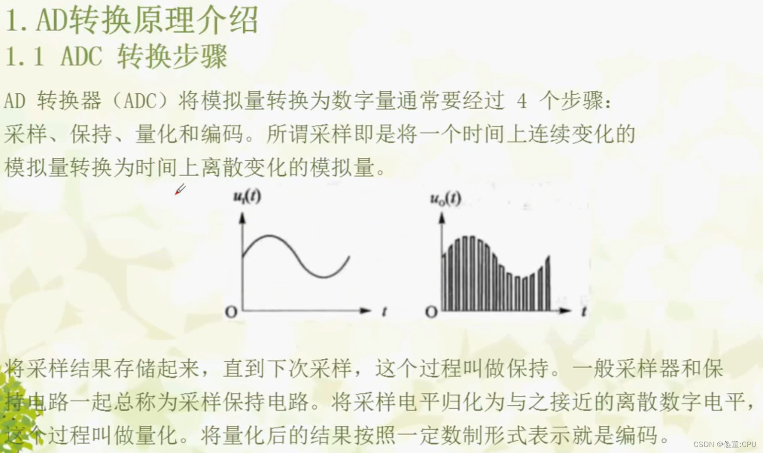
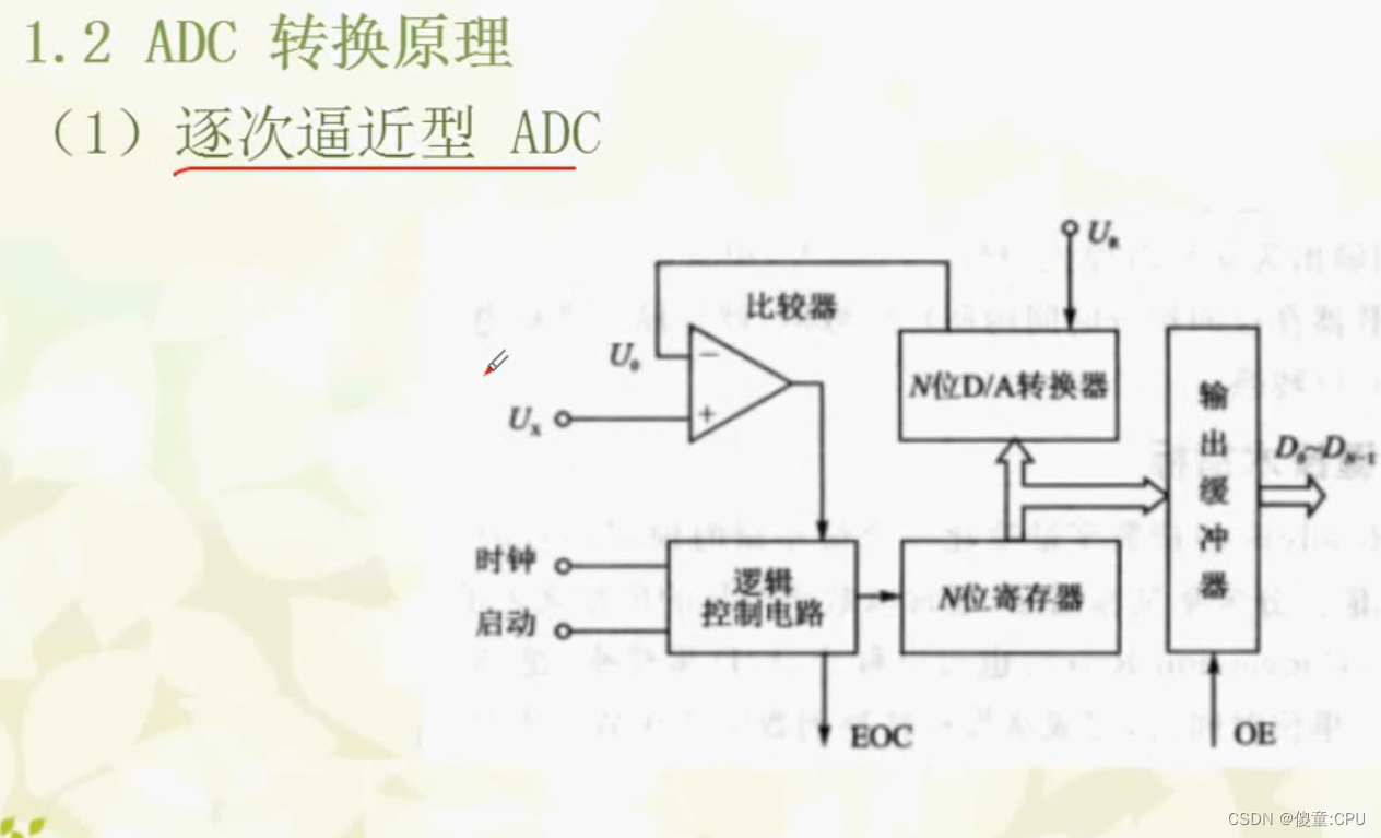
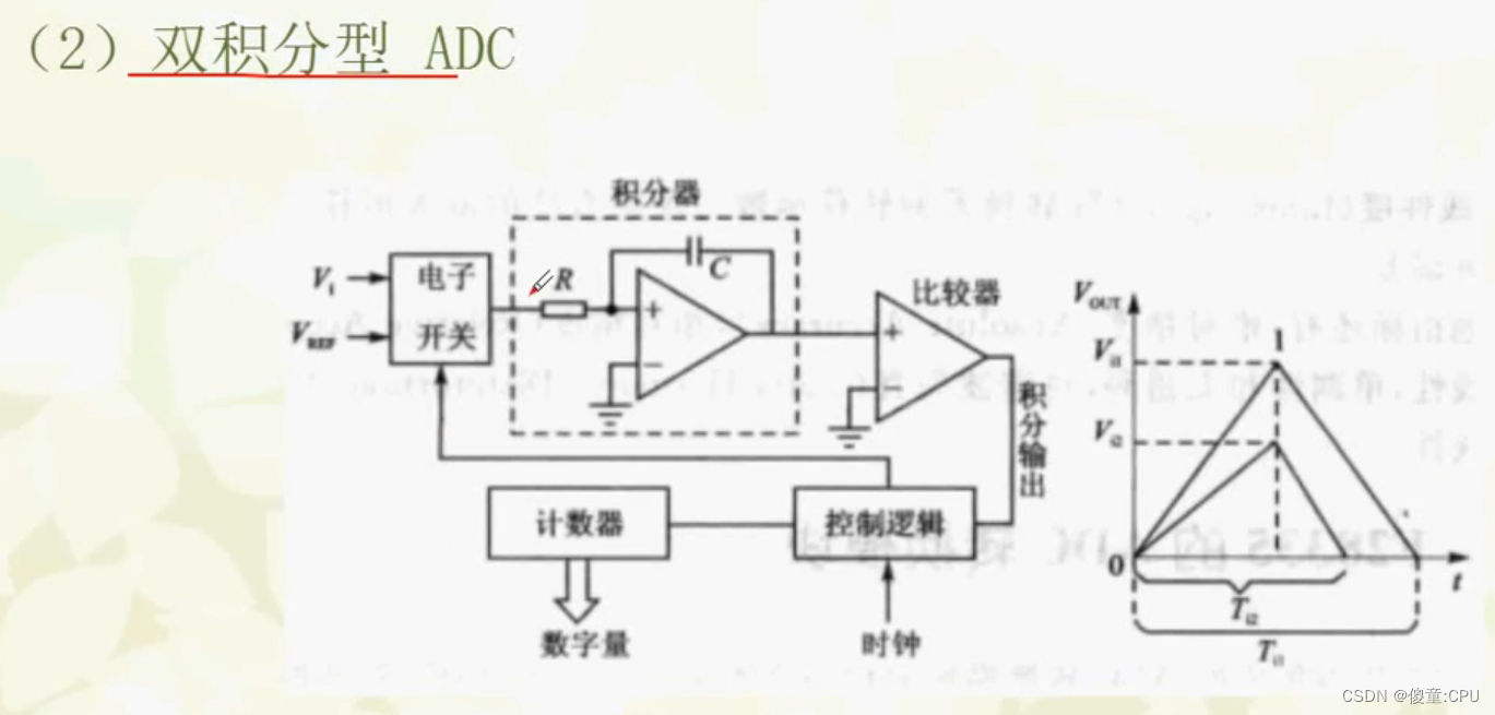
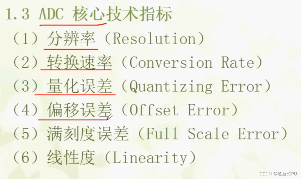
1 AD 转换原理介绍

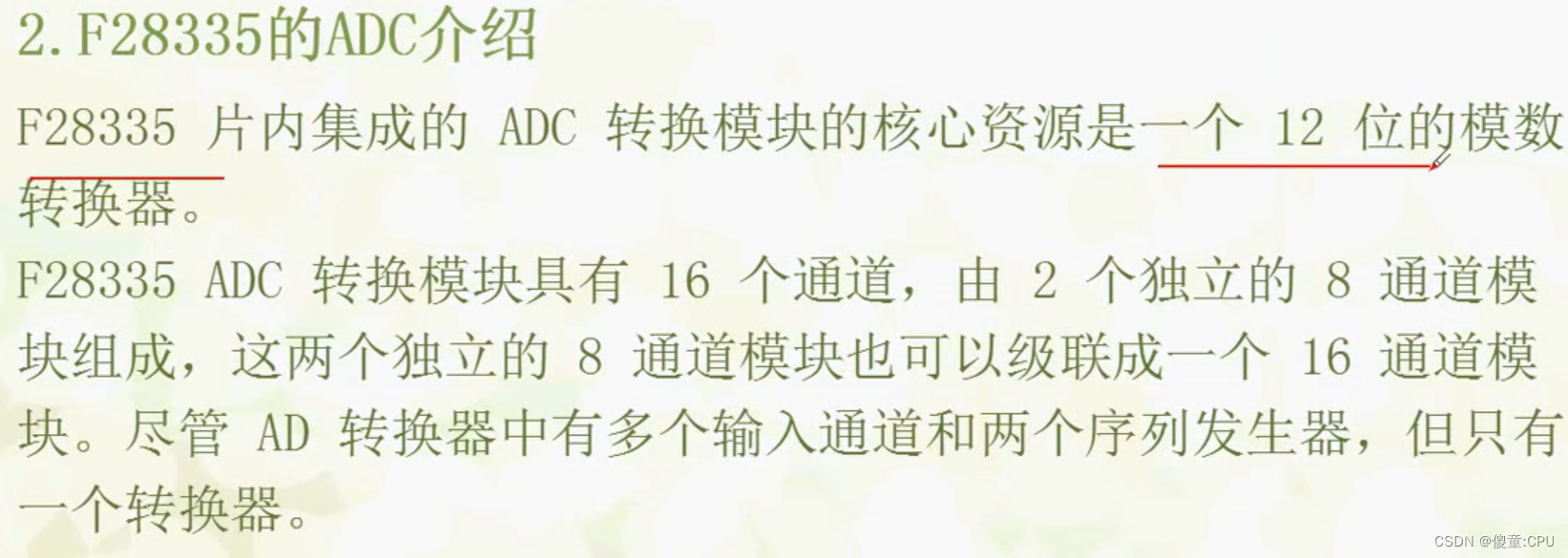
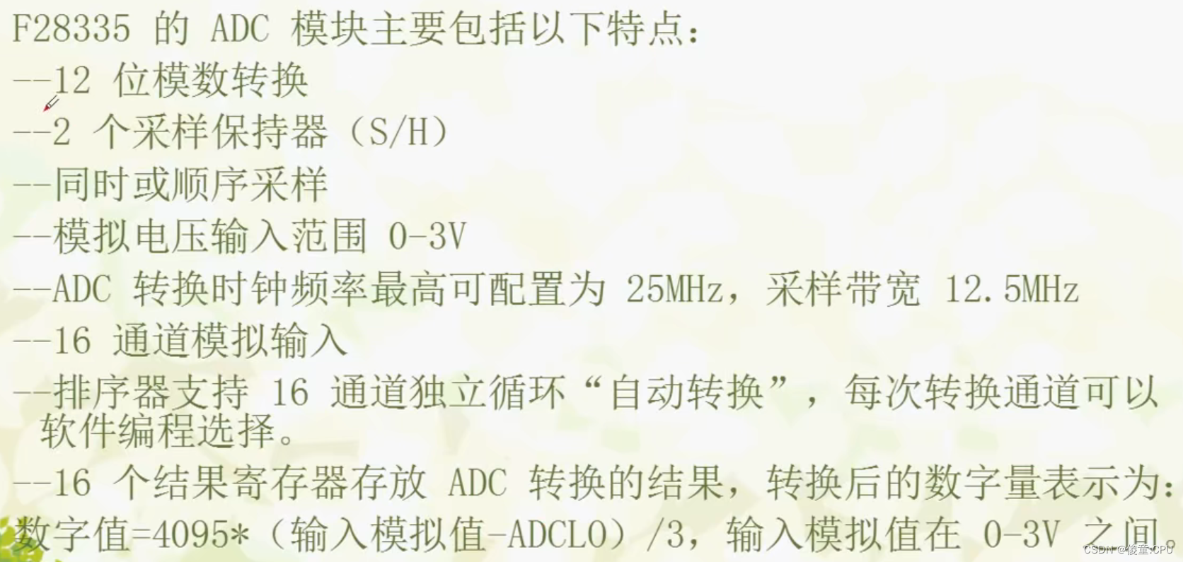
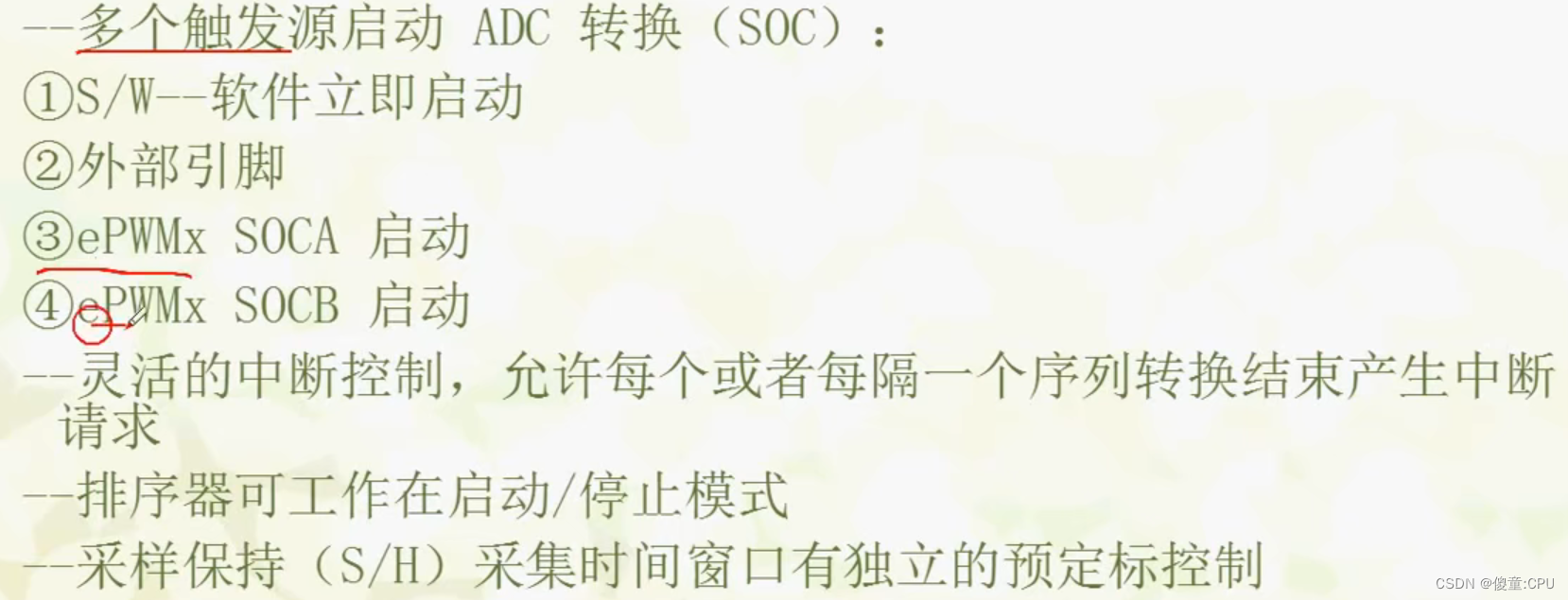
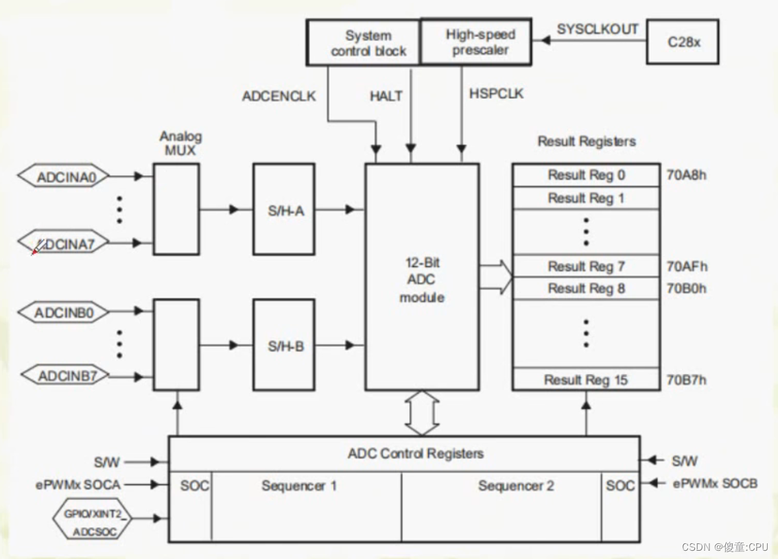
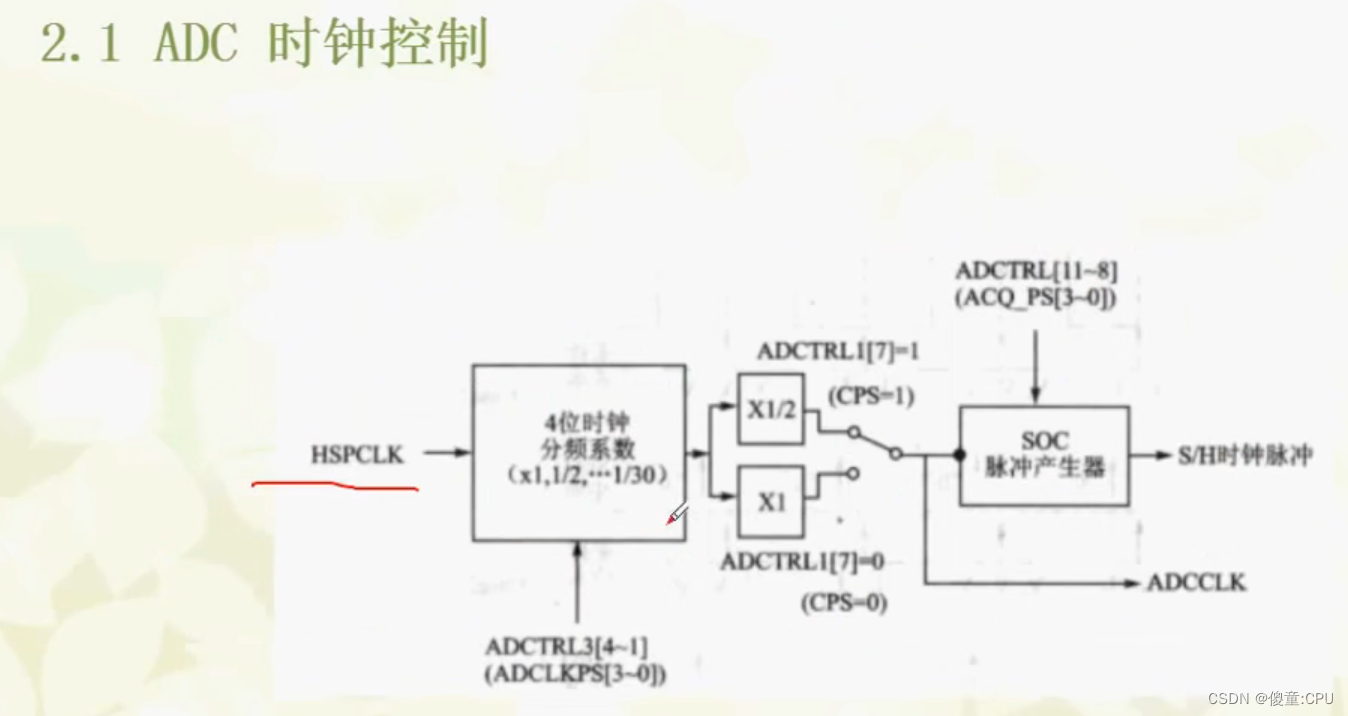
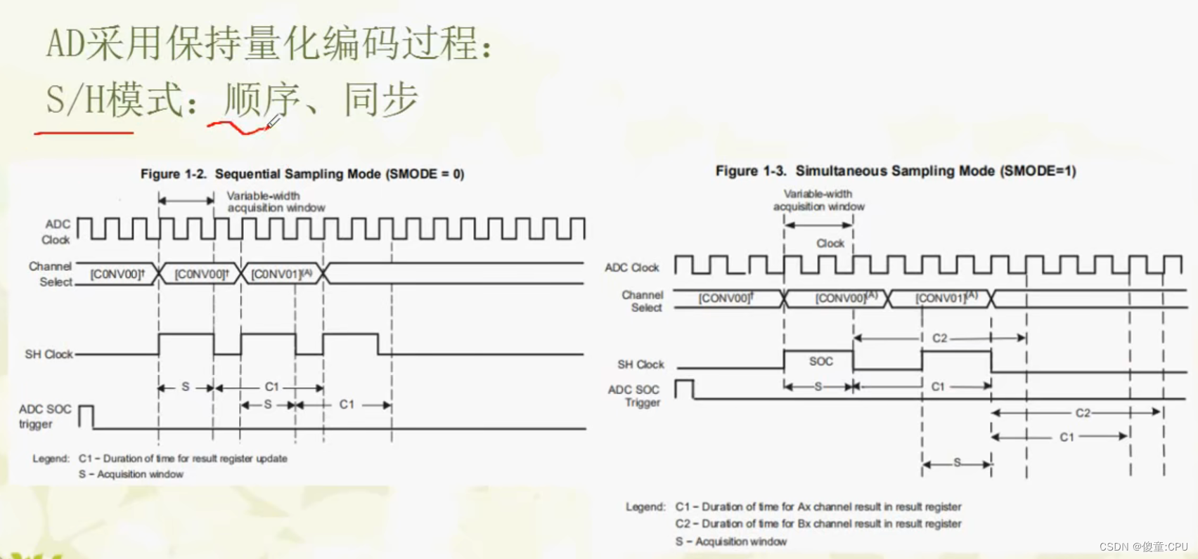
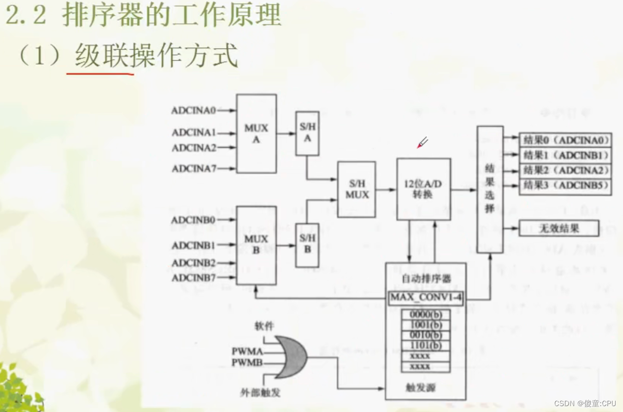
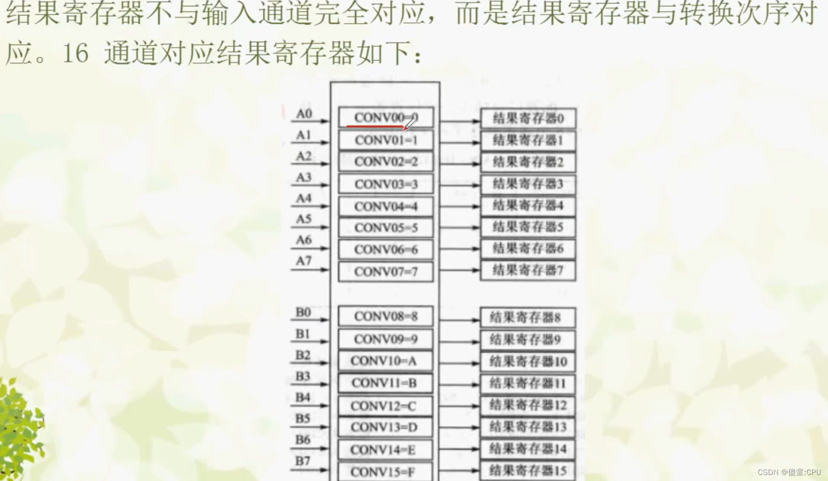
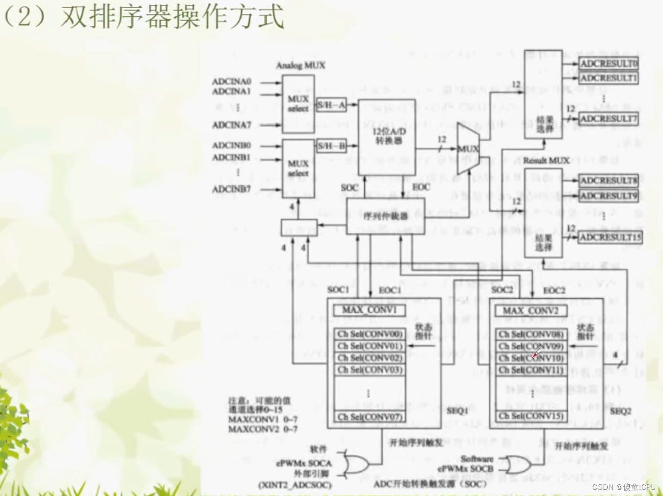
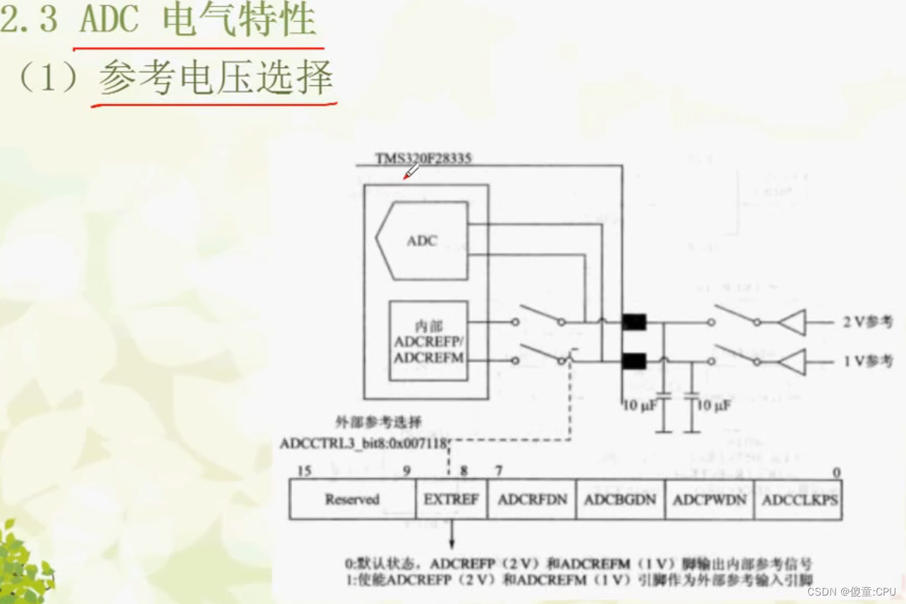
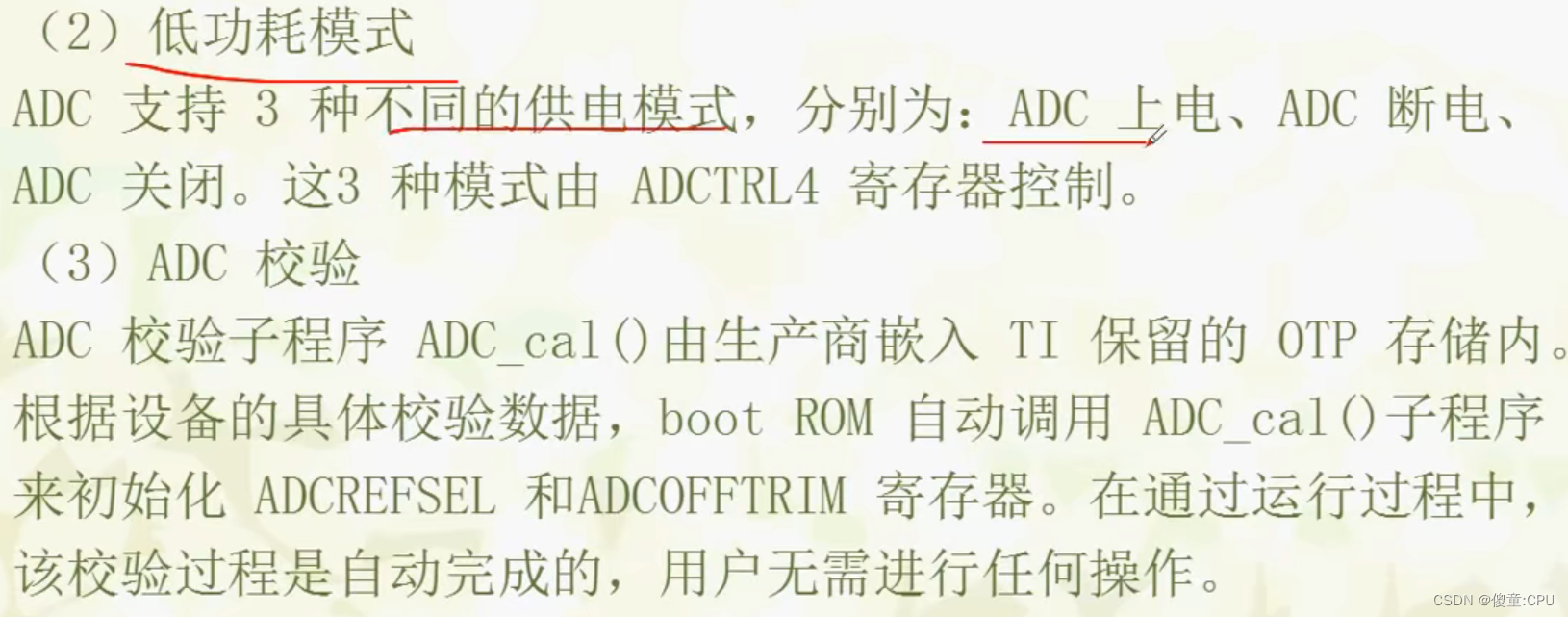
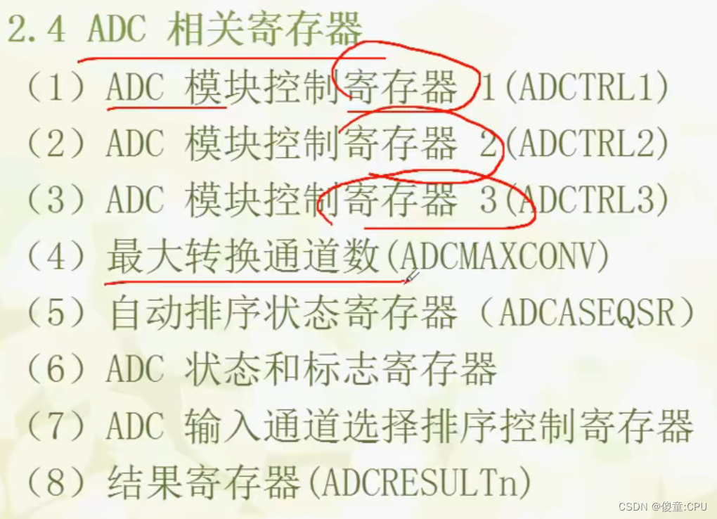
2 F28335的ADC介绍

3 ADC配置步骤
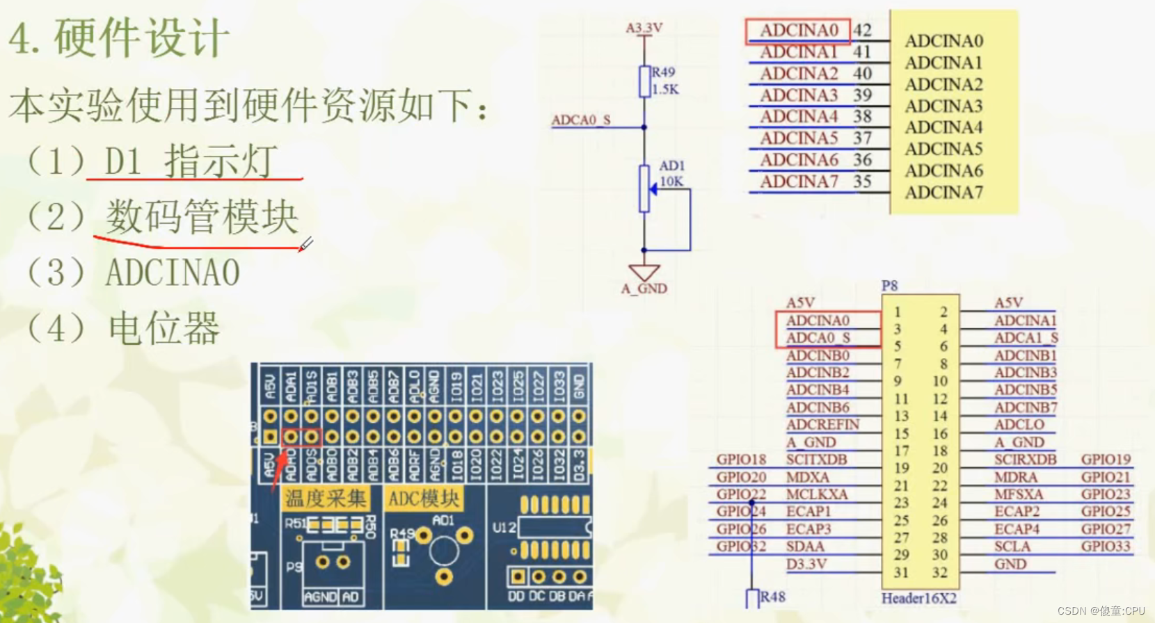
4 硬件设计
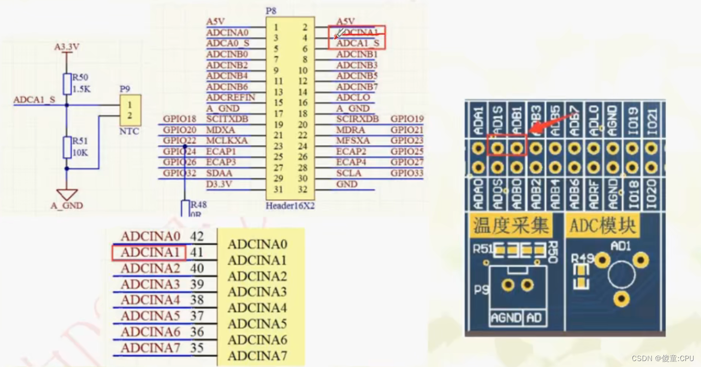
5 软件设计

#include "adc.h"


void ADC_Init(void)
{
	// Specific clock setting for this example:
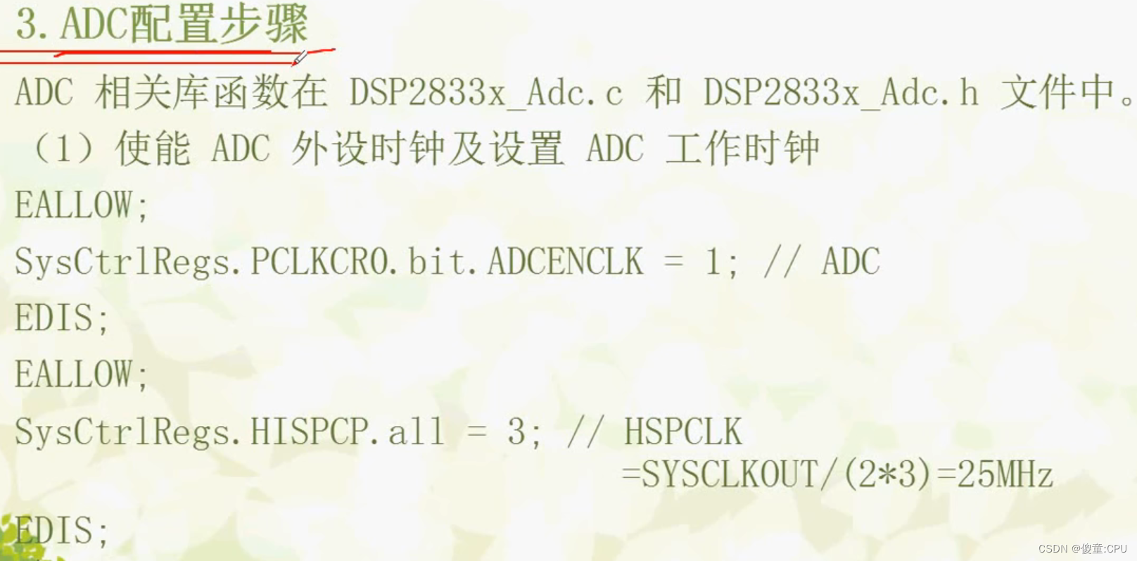
	EALLOW;
	SysCtrlRegs.PCLKCR0.bit.ADCENCLK = 1;    // ADC
	EDIS;

	// Specific clock setting for this example:
	EALLOW;
	SysCtrlRegs.HISPCP.all = ADC_MODCLK;	// HSPCLK = SYSCLKOUT/(2*ADC_MODCLK)
	EDIS;

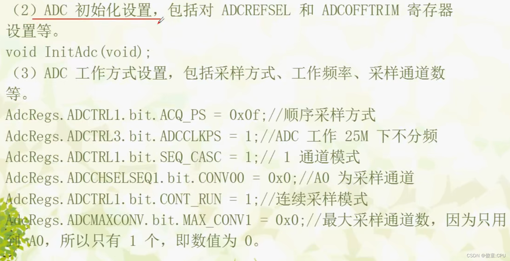
	InitAdc();  // For this example, init the ADC

	// Specific ADC setup for this example:
	AdcRegs.ADCTRL1.bit.ACQ_PS = ADC_SHCLK;
	AdcRegs.ADCTRL3.bit.ADCCLKPS = ADC_CKPS;
	AdcRegs.ADCTRL1.bit.SEQ_CASC = 1;        // 1  Cascaded mode
	AdcRegs.ADCCHSELSEQ1.bit.CONV00 = 0x0;
	AdcRegs.ADCTRL1.bit.CONT_RUN = 1;       // Setup continuous run
	AdcRegs.ADCMAXCONV.bit.MAX_CONV1 = 0x0;

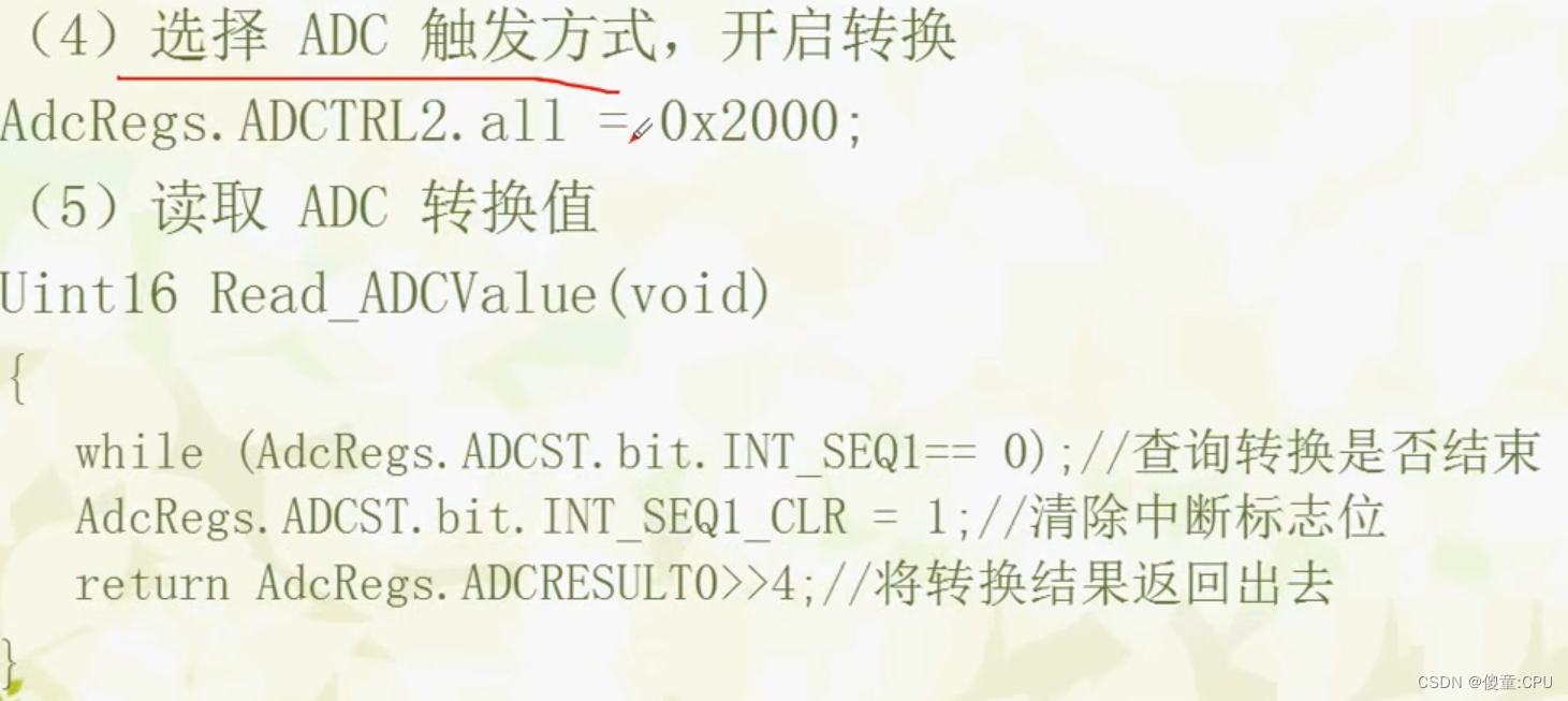
	// Start SEQ1
	AdcRegs.ADCTRL2.all = 0x2000;

}

Uint16 Read_ADCValue(void)
{
	while (AdcRegs.ADCST.bit.INT_SEQ1== 0);
	AdcRegs.ADCST.bit.INT_SEQ1_CLR = 1;
	return AdcRegs.ADCRESULT0>>4;
}
#ifndef ADC_H_
#define ADC_H_

#include "DSP2833x_Device.h"     // DSP2833x 头文件
#include "DSP2833x_Examples.h"   // DSP2833x 例子相关头文件


#define ADC_MODCLK 3
#define ADC_CKPS   0x1   // ADC module clock = HSPCLK/2*ADC_CKPS   = 25.0MHz/(1*2) = 12.5MHz
#define ADC_SHCLK  0xf   // S/H width in ADC module periods                        = 16 ADC clocks


void ADC_Init(void);
Uint16 Read_ADCValue(void);

#endif /* ADC_H_ */
#include "DSP2833x_Device.h"     // DSP2833x Headerfile Include File
#include "DSP2833x_Examples.h"   // DSP2833x Examples Include File

#include "leds.h"
#include "time.h"
#include "smg.h"
#include "adc.h"


/*******************************************************************************
* 函 数 名         : main
* 函数功能		   : 主函数
* 输    入         : 无
* 输    出         : 无
*******************************************************************************/
void main()
{
	int i=0;
	float adc_vol;

	InitSysCtrl();

	InitPieCtrl();
	IER = 0x0000;
	IFR = 0x0000;
	InitPieVectTable();

	LED_Init();
	TIM0_Init(150,200000);//200ms
	SMG_Init();
	ADC_Init();

	while(1)
	{
		adc_vol=(float)Read_ADCValue()*3.0/4096;
		SMG_DisplayFloat(adc_vol,2);
//		SMG_DisplayInt(Read_ADCValue());

	}
}
