目录
1、参考网上的程序编写SPI读写函数
? ? ? ? w25q32可使用spi模式0和模式3.
	u8 redata;

u8 SPI_FLASH_SendByte(u8 data)
{
	u8 i;
	u16 j=0;
	redata = 0;
	for(i=0;i<8;i++)
	{
//		for(j=0;j<12;j++)
//			__nop();

		if(data & 0x80)
			SPI_MOSI_1;
		else
			SPI_MOSI_0;
		data <<= 1;

		SPI_SCK_0;

		for(j=0;j<12;j++)
			__nop();

		SPI_SCK_1;

		for(j=0;j<8;j++)
			__nop();

		redata<<=1;

		if(SPI_MISO)
			redata++;
	}
	for(j=0;j<20;j++)
			__nop();
	SPI_SCK_1;
	return redata;
}
2、参考w25q32的例程读取芯片ID
///*******************************************************************************
//* Function Name  : SPI_FLASH_ReadID
//* Description    : Reads FLASH identification.
//* Input          : None
//* Output         : None
//* Return         : FLASH identification
//*******************************************************************************/
u32 SPI_FLASH_ReadDeviceID(void)
{
	u32 Temp = 0;

//	/* Select the FLASH: Chip Select low */
//	SPI_FLASH_CS_LOW();

//	/* Send "RDID " instruction */
	SPI_FLASH_SendByte(W25X_DeviceID);
//	SPI_FLASH_SendByte(W25X_DeviceID);
//	SPI_FLASH_SendByte(Dummy_Byte);
//	SPI_FLASH_SendByte(Dummy_Byte);
//	SPI_FLASH_SendByte(Dummy_Byte);

//	/* Read a byte from the FLASH */
//	Temp = SPI_FLASH_SendByte(Dummy_Byte);

//	/* Deselect the FLASH: Chip Select high */
//	SPI_FLASH_CS_HIGH();

//	return Temp;


	u16 j=0;

	/* Select the FLASH: Chip Select low */
	SPI_FLASH_CS_LOW();
	for(j=0;j<100;j++)
			__nop();
//	__nop();
	/* Send "RDID " instruction */
//	SPI_FLASH_SendByte(W25X_DeviceID);
	SPI_FLASH_SendByte(0x90);
//	__nop();
	SPI_FLASH_SendByte(0x00);
//	__nop();
	SPI_FLASH_SendByte(0x00);
//	__nop();
	SPI_FLASH_SendByte(0x00);
//	__nop();

	/* Read a byte from the FLASH */
	Temp |= SPI_FLASH_SendByte(0xFF);
	Temp = Temp<<8;
//	__nop();
	Temp |= SPI_FLASH_SendByte(0xFF);

	/* Deselect the FLASH: Chip Select high */
//	for(j=0;j<100;j++)
//			__nop();
	SPI_FLASH_CS_HIGH();

	return Temp;
}
3、读取芯片ID时遇到的问题
问题1:没有返回数据
? ? ? ? 排查是解析错误。
问题2:返回芯片ID错误
? ? ? ? 芯片ID应该是0xEF15,结果返回的是0xDC1D,然后是0xEE1E。
????????首先是怀疑各种延时不对,然后怀疑各种空闲时的电平不对,一通调整,还是不对。
? ? ? ? 然后使用st开发板上的硬件spi读取,发现读取到的ID是对的,可以证明模块没有问题。
? ? ? ? 然后使用逻辑分析仪对比两个板子上的波形:
? ? ? ? 错误数据的波形:

? ? ? ? ?正确数据的波形:

?????????对比后发现时序也没有问题,然后怀疑是不是spi速率的问题,之后将spi的速率调整为和开发板的一样,还是不行,然后换衣是不是在下降沿之后写入数据太晚了,调整为在下降沿之前写入数据,发现还是不行。。。。。。
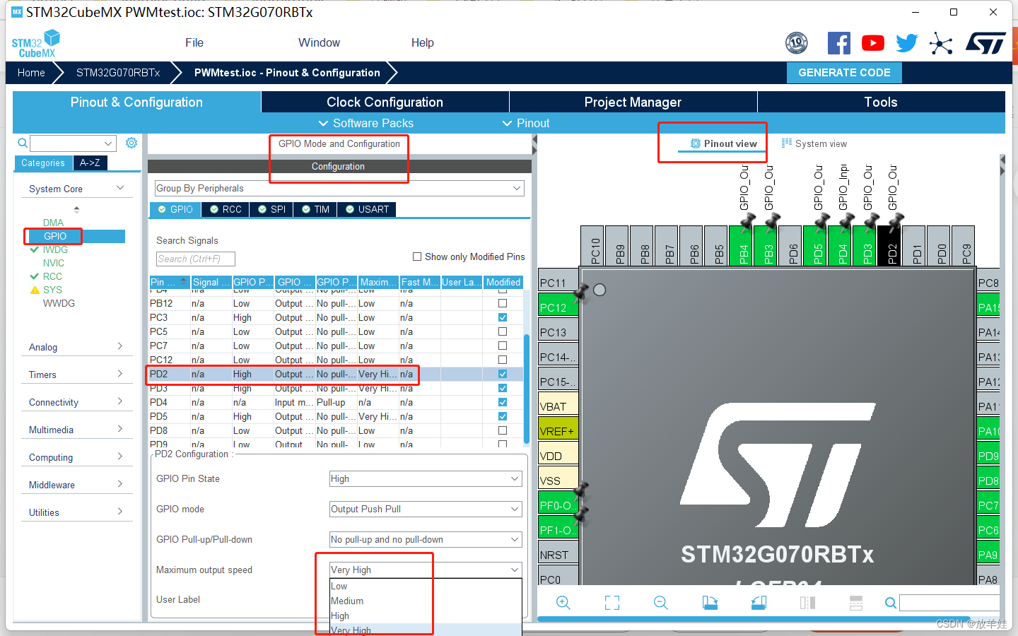
? ? ? ? 最后发现是IO的速率设置的太低了,因为是使用cubemx生成的配置程序,没有注意IO里面的速率设置:

?????????然后把所有的io都设置为高速率就可以了。
????????单个IO设置为高速率测试发现:只要MOSI引脚设置为高速率就行,那么推测可能的原因是在MOSI引脚跳变时间较长,导致从设备采集到错误的电平,虽然逻辑分析仪看到的是对的,这种情况在示波器上应该是可以观测到的,但是没有好用的示波器。。。。。。
4、优化后的收发函数和时序波形
u8 SPI_FLASH_SendByte(u8 data)
{
	u8 i = 0, redata = 0;
	for(i=0;i<8;i++)
	{
		SPI_SCK_0;	// Falling edge to write the sent data
		if(data & 0x80)
			SPI_MOSI_1;
		else
			SPI_MOSI_0;
		data <<= 1;
		SPI_SCK_1;	// Rising edge, reading data
		redata<<=1;
		if(SPI_MISO)
			redata++;
	}
	__nop();
	return redata;
}
?????????时序简言之:在时钟下降沿的时候将数据写入数据线,在时钟上升沿的时候会去采集数据线上的数据。
