前言
本文将介绍陀螺仪和加速度计的使用程序和校准方法,STM32的程序代码可从文章末尾获得。
一、陀螺仪与加速度计简介
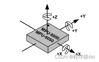
陀螺仪的理解可以从单位入手,测量值的单位是°/s。意思是某时刻的旋转角度的变化速度是每秒多少度。加速度计则容易理解很多,单位为g,这里就不多阐述。下面是MPU6050三轴的方向图。

二、程序使用
文章末尾可获取STM32F103C8T6的程序,可稍微更改一下就能移植到别的平台。硬件连线如下:
- PB5 --> INT
- PB6 --> SCL
- PB7 --> SDA
- PA9,PA10–>串口
1.初始化
MPU6050的初始化函数如下。这里提供了一般的初始化设置,也可自行根据寄存器手册进行修改。
/************************************
* 函数功能:传感器初始化
* 参数:无
* 返回值: 0 初始化成功
* 1 初始化失败
*************************************/
uint8_t mpu6050_init(void)
{
uint8_t temp;
uint8_t param[] = {0,0x03,0x18,0x10,0x10,0x01};
mpu6050_i2c_readMem(MPU6050_WHO_AM_I,&temp,1);
if(temp != 0x68)
{
// printf("不能读取寄存器,初始化失败");
return 1;
}
temp = 0x80;
mpu6050_i2c_writeMem(MPU6050_PWR_MGMT_1,&temp); //重启设备
delay_ms(100);
temp = 0;
mpu6050_i2c_writeMem(MPU6050_PWR_MGMT_1,&temp); //退出休眠模式
mpu6050_i2c_writeMem(MPU6050_SMPLRT_DIV,¶m[0]); //Sample Rate = Gyroscope Output Rate / (1 + SMPLRT_DIV) = 1kHz
mpu6050_i2c_readMem(MPU6050_SMPLRT_DIV,&temp,1); //其中Gyroscope Output Rate=1kHz 或 8kHz 取决于是否开启数字低通滤波器
if(temp != param[0])
return 1;
mpu6050_i2c_writeMem(MPU6050_CONFIG,¶m[1]); //失能低通滤波器,带宽: 加速度 44Hz; 陀螺仪 42Hz
mpu6050_i2c_readMem(MPU6050_CONFIG,&temp,1);
if(temp != param[1])
return 1;
mpu6050_i2c_writeMem(MPU6050_GYRO_CONFIG,¶m[2]); //陀螺仪量程:± 2000 °/s
mpu6050_i2c_readMem(MPU6050_GYRO_CONFIG,&temp,1);
if(temp != param[2])
return 1;
mpu6050_i2c_writeMem(MPU6050_ACCEL_CONFIG,¶m[3]); //加速度量程:± 8g
mpu6050_i2c_readMem(MPU6050_ACCEL_CONFIG,&temp,1);
if(temp != param[3])
return 1;
mpu6050_i2c_writeMem(MPU6050_INT_PIN_CFG,¶m[4]); //中断引脚设置
mpu6050_i2c_readMem(MPU6050_INT_PIN_CFG,&temp,1);
if(temp != param[4])
return 1;
mpu6050_i2c_writeMem(MPU6050_INT_ENABLE,¶m[5]); //中断引脚使能
mpu6050_i2c_readMem(MPU6050_INT_ENABLE,&temp,1);
if(temp != param[5])
return 1;
//printf("初始化成功");
return 0;
}
2.读取数据
以下为读取陀螺仪数据的函数,读取到的数据为ADC的原始数据,需要根据ADC的分辨率将单位转换为°/s。加速度计的数据读取也类似,不再赘述。
/************************************
*	函数功能:获得陀螺仪原始数据
*	参数: *GYRO	接收数据的指针
*	返回值: 无
*************************************/
void mpu6050_getRawGyro(mpu6050_data *pGyro)
{
	uint8_t rawData[6];
	int16_t rawGyroData[3];
	mpu6050_i2c_readMem(MPU6050_GYRO_XOUT_H,rawData,6);

	rawGyroData[0] = (int16_t)((uint16_t)rawData[0]<<8)|((uint16_t)rawData[1]);
	rawGyroData[1] = (int16_t)((uint16_t)rawData[2]<<8)|((uint16_t)rawData[3]);
	rawGyroData[2] = (int16_t)((uint16_t)rawData[4]<<8)|((uint16_t)rawData[5]);

	pGyro->x = ((float)rawGyroData[0]) * gyro_raw_to_deg_s;
	pGyro->y = ((float)rawGyroData[1]) * gyro_raw_to_deg_s;
	pGyro->z = ((float)rawGyroData[2]) * gyro_raw_to_deg_s;

	pGyro->x -= gyro_offest[0];
	pGyro->y -= gyro_offest[1];
	pGyro->z -= gyro_offest[2];
}
三、误差校准
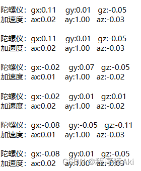
一般来说,MEMS(微机电系统)器件由于制造工艺精度问题,都会存在一定的误差。下图是静止在水平面的条件下测试得到的数值。可见,水平静止的情况下,陀螺仪输出应该为0,加速度计Z轴输出应为1g。所以出现了较大误差。

1.陀螺仪校准
陀螺仪的校准相对简单。在静止的情况下,将多个采样的平均值作为偏置值。测量后减去这个零偏即为真实值。若存在零偏,即使在静止的情况下,得出的数据会认为正在旋转,随着时间累积会出现较大误差。
const float gyro_offest[3] = {-0.96,0.902,-1.05};

	pRogy->x -= gyro_offest[0];
	pRogy->y -= gyro_offest[1];
	pRogy->z -= gyro_offest[2];                          //校准
2.加速度计校准
加速度计校准可建立以下数学模型。

使用matlab的lsqcurvefit函数进行拟合,解出6个参数。具体matlab代码示例如下:
clear;clc;
axm=[0.007813   0.100098   0.066162   0.031982   1.070068    -0.939697];
aym=[-0.061279  -0.019043  -1.013916  0.979248   -0.018555   -0.023438];
azm=[0.929688   -1.088379  -0.096191  -0.079346  -0.172607   -0.054932];
am=[axm',aym',azm']; %axm, aym, azm分别是采集的三轴加速度计数据,最好是6个面进行采集
G=[1 1 1 1 1 1]';
f=@(a,am)(a(1)*am(:,1)+a(2)).^2+(a(3)*am(:,2)+a(4)).^2+(a(5)*am(:,3)+a(6)).^2;
a0=[1 0 1 0 1 0];
a=lsqcurvefit(f,a0,am,G)
以下是解出的参数和校准代码。
const float acc_param_k[3] = {0.9928,1.0030,0.9894};
const float acc_param_a[3] = {-0.0668,0.0172,0.0774};

	pAcc->x = acc_param_k[0] * pAcc->x + acc_param_a[0];
	pAcc->y = acc_param_k[1] * pAcc->y + acc_param_a[1];
	pAcc->z = acc_param_k[2] * pAcc->z + acc_param_a[2];
3.校准后的输出
可见,校准后的输出误差明显减少。

四、源码获取
关注下方公众号,回复 “MPU6050” 获取源码;若有疑问,请在公众号回复“交流群”,进群一起讨论分享!

