个人学习记录
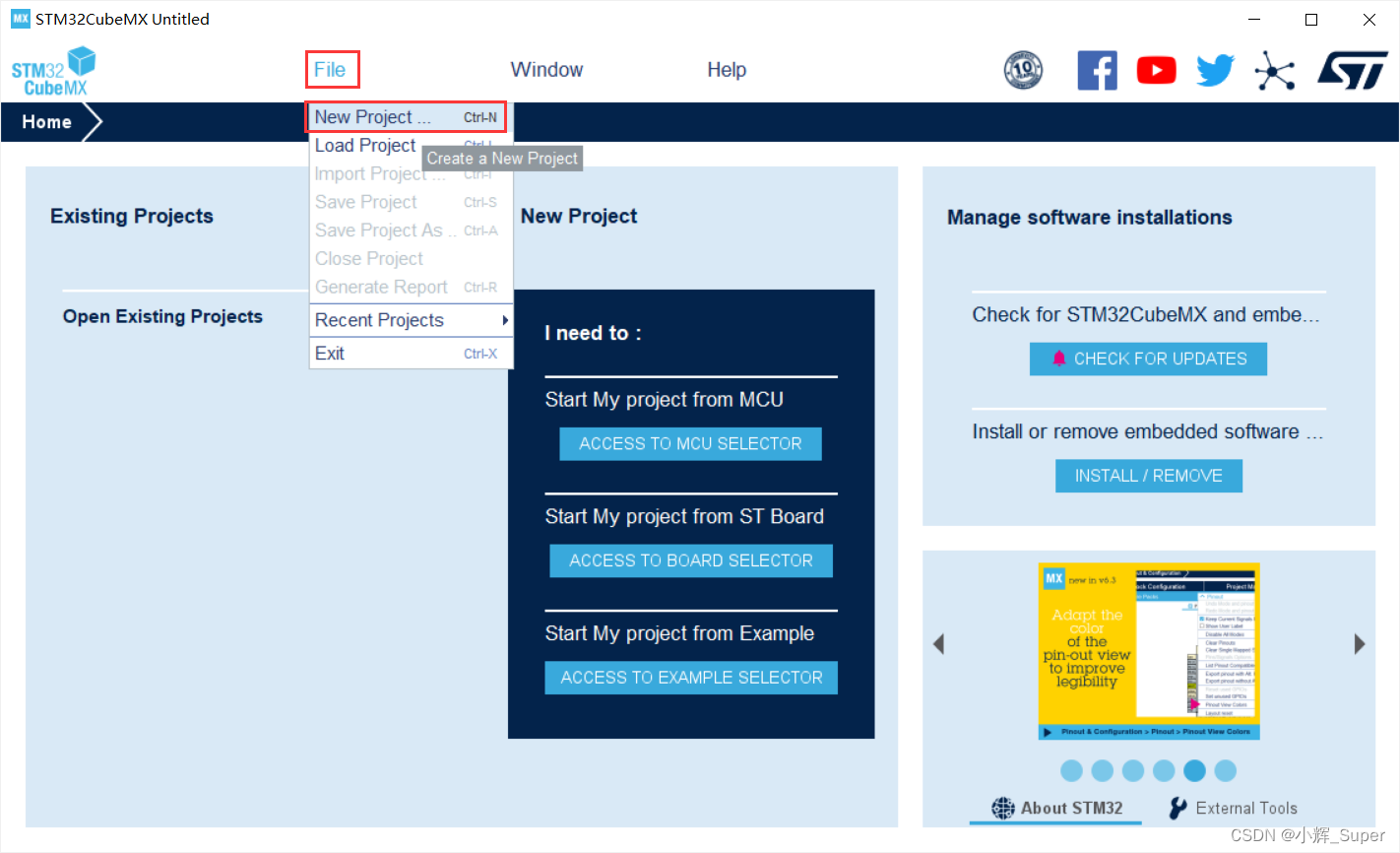
一、新建工程
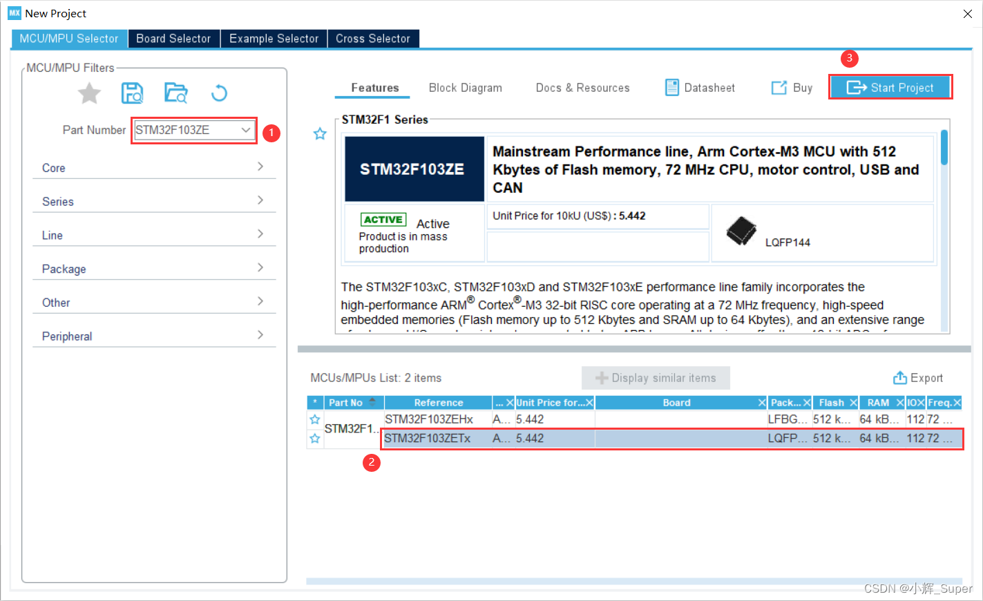
二、选择芯片型号
我使用的开发板是正点原子 STM32F103ZET6 核心板
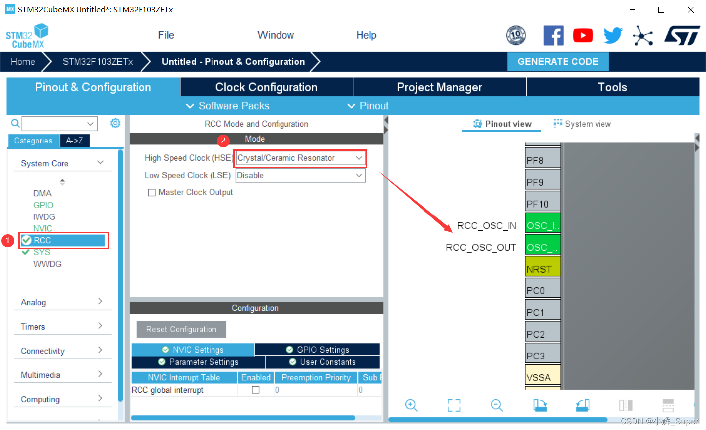
三、配置时钟
开发板焊接了外部晶振,所以我 RCC(Reset and Cock Control) 配置选择了 Crystal/Ceramic Resonator(石英/陶瓷谐振器),配置完成后,右边的 Pinout view 里相关引脚就会被标绿。
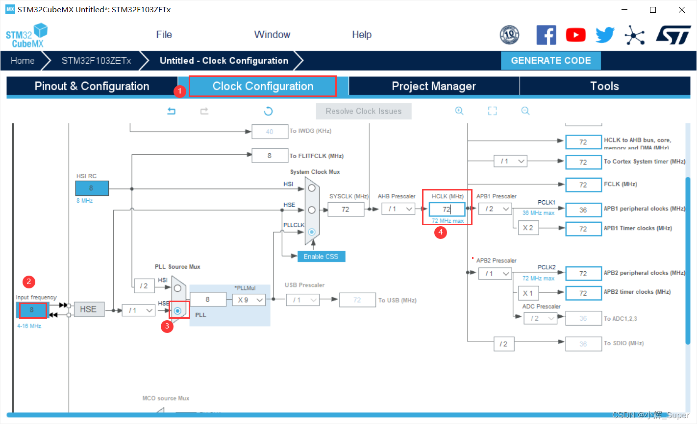
外部高速时钟配置完成后,进入 Clock Configuration 选项,根据实际情况,将系统时钟配置为 72 MHz,配置步骤如下,最后按下回车,软件会自动调整分频和倍频参数。
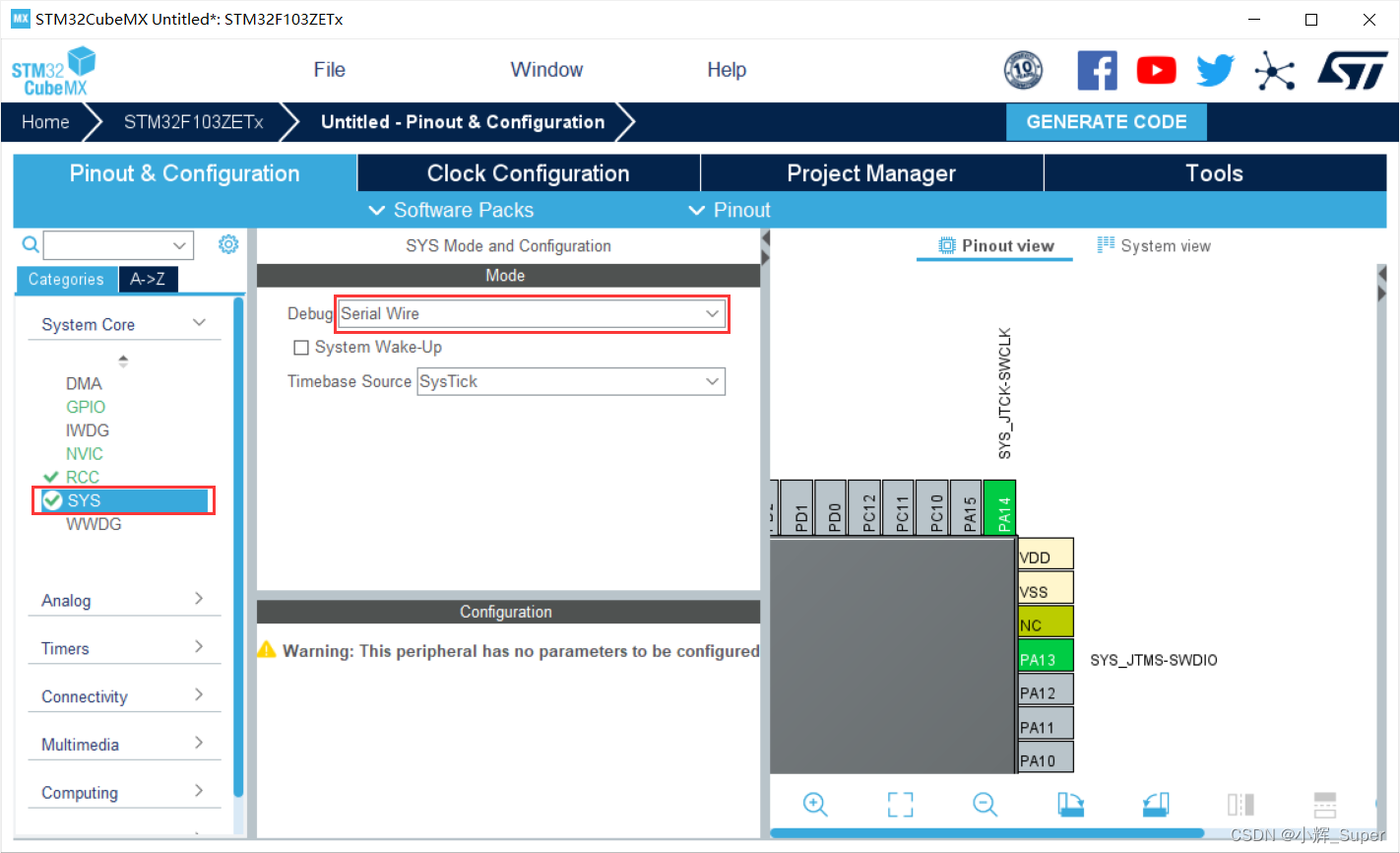
四、配置调试模式
ST-Link 就是 Serial Wire 调试模式,一定要设置!!!
以前使用 M0 的芯片,不配置这个模式没出现问题,但现在这个型号,如果不配置 Serial Wire 模式,程序一旦通过 ST-Link 烧录到芯片中,芯片就再也不能被ST-Link 识别了。(后来我是通过 STMISP 工具烧录程序/擦除后才恢复正常的)
五、定时器参数配置
我们选择通用定时器 TIM3 来实验,具体的参数配置如下(7200 预分配,周期为 5000,自动重装载)

分频系数为 7200-1,意思就是 7200 分频(0表示 1 分频,1 表示 2 分频,以此类推),TIM3 的时钟频率为 72 MHz(见下面两张图)。将其进行 7200 分频后,频率变成了 10000 Hz,即每秒计数 10000 次。假如我们需要每 500ms 触发一次超时中断,计数周期就要设置为 5000-1(这里要减一,应该是因为计数值最小为 0)。


不要忘了使能中断:

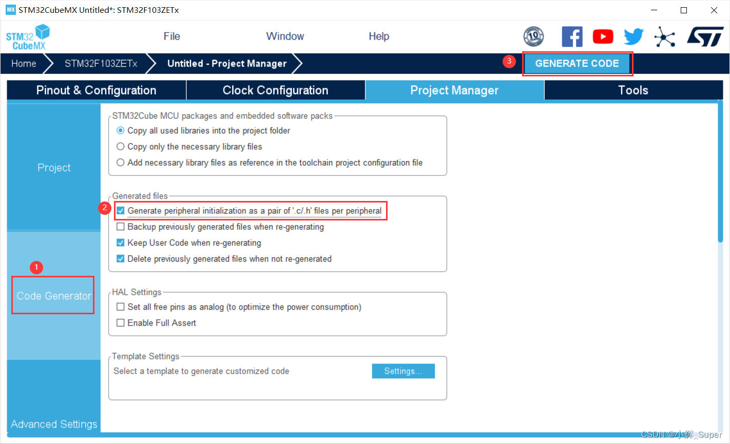
六、生成 Keil 工程
设置 IDE 和 工程目录及名称:

将每种外设的代码存放到不同的 .c /.h 文件中,便于管理(不然都会被放到 main.c 中)。
下面是生成 Keil 工程中关于 TIM3 初始化的代码:

七、测试示例
HAL_TIM_PeriodElapsedCallback() 是一个回调函数,当定时器超时中断被触发时,该函数会自动运行,我在定时器中断里实现了 PB5 的翻转(还需要在 STM32CubeMx 中配置 PB5,PB5 在我所用的开发板上被用来控制 LED)。
/* USER CODE BEGIN Header */
/**
  ******************************************************************************
  * @file           : main.c
  * @brief          : Main program body
  ******************************************************************************
  * @attention
  *
  * Copyright (c) 2022 STMicroelectronics.
  * All rights reserved.
  *
  * This software is licensed under terms that can be found in the LICENSE file
  * in the root directory of this software component.
  * If no LICENSE file comes with this software, it is provided AS-IS.
  *
  ******************************************************************************
  */
/* USER CODE END Header */
/* Includes ------------------------------------------------------------------*/
#include "main.h"
#include "tim.h"
#include "gpio.h"

/* Private includes ----------------------------------------------------------*/
/* USER CODE BEGIN Includes */

/* USER CODE END Includes */

/* Private typedef -----------------------------------------------------------*/
/* USER CODE BEGIN PTD */

extern TIM_HandleTypeDef htim3;

/* USER CODE END PTD */

/* Private define ------------------------------------------------------------*/
/* USER CODE BEGIN PD */
/* USER CODE END PD */

/* Private macro -------------------------------------------------------------*/
/* USER CODE BEGIN PM */

/* USER CODE END PM */

/* Private variables ---------------------------------------------------------*/

/* USER CODE BEGIN PV */

/* USER CODE END PV */

/* Private function prototypes -----------------------------------------------*/
void SystemClock_Config(void);
/* USER CODE BEGIN PFP */

/* USER CODE END PFP */

/* Private user code ---------------------------------------------------------*/
/* USER CODE BEGIN 0 */

/* USER CODE END 0 */

/**
  * @brief  The application entry point.
  * @retval int
  */
int main(void)
{
  /* USER CODE BEGIN 1 */

  /* USER CODE END 1 */

  /* MCU Configuration--------------------------------------------------------*/

  /* Reset of all peripherals, Initializes the Flash interface and the Systick. */
  HAL_Init();

  /* USER CODE BEGIN Init */

  /* USER CODE END Init */

  /* Configure the system clock */
  SystemClock_Config();

  /* USER CODE BEGIN SysInit */

  /* USER CODE END SysInit */

  /* Initialize all configured peripherals */
  MX_GPIO_Init();
  MX_TIM3_Init();
  /* USER CODE BEGIN 2 */

  HAL_TIM_Base_Start_IT(&htim3);  //启动定时器TIM3

  /* USER CODE END 2 */

  /* Infinite loop */
  /* USER CODE BEGIN WHILE */
  while (1)
  {
    /* USER CODE END WHILE */

    /* USER CODE BEGIN 3 */
  }
  /* USER CODE END 3 */
}

/**
  * @brief System Clock Configuration
  * @retval None
  */
void SystemClock_Config(void)
{
  RCC_OscInitTypeDef RCC_OscInitStruct = {0};
  RCC_ClkInitTypeDef RCC_ClkInitStruct = {0};

  /** Initializes the RCC Oscillators according to the specified parameters
  * in the RCC_OscInitTypeDef structure.
  */
  RCC_OscInitStruct.OscillatorType = RCC_OSCILLATORTYPE_HSE;
  RCC_OscInitStruct.HSEState = RCC_HSE_ON;
  RCC_OscInitStruct.HSEPredivValue = RCC_HSE_PREDIV_DIV1;
  RCC_OscInitStruct.HSIState = RCC_HSI_ON;
  RCC_OscInitStruct.PLL.PLLState = RCC_PLL_ON;
  RCC_OscInitStruct.PLL.PLLSource = RCC_PLLSOURCE_HSE;
  RCC_OscInitStruct.PLL.PLLMUL = RCC_PLL_MUL9;
  if (HAL_RCC_OscConfig(&RCC_OscInitStruct) != HAL_OK)
  {
    Error_Handler();
  }
  /** Initializes the CPU, AHB and APB buses clocks
  */
  RCC_ClkInitStruct.ClockType = RCC_CLOCKTYPE_HCLK|RCC_CLOCKTYPE_SYSCLK
                              |RCC_CLOCKTYPE_PCLK1|RCC_CLOCKTYPE_PCLK2;
  RCC_ClkInitStruct.SYSCLKSource = RCC_SYSCLKSOURCE_PLLCLK;
  RCC_ClkInitStruct.AHBCLKDivider = RCC_SYSCLK_DIV1;
  RCC_ClkInitStruct.APB1CLKDivider = RCC_HCLK_DIV2;
  RCC_ClkInitStruct.APB2CLKDivider = RCC_HCLK_DIV1;

  if (HAL_RCC_ClockConfig(&RCC_ClkInitStruct, FLASH_LATENCY_2) != HAL_OK)
  {
    Error_Handler();
  }
}

/* USER CODE BEGIN 4 */

/******************************************************************************
 * @ 函数名  : HAL_TIM_PeriodElapsedCallback
 * @ 功  能  : 定时器超时中断回调函数
 * @ 参  数  : huart 串口名
 * @ 返回值  : 无
 ******************************************************************************/
void HAL_TIM_PeriodElapsedCallback(TIM_HandleTypeDef *htim)
{
   if(htim->Instance == TIM3)
   {
      HAL_GPIO_TogglePin(GPIOB, GPIO_PIN_5); //对PB5进行翻转
   }
}

/* USER CODE END 4 */

/**
  * @brief  This function is executed in case of error occurrence.
  * @retval None
  */
void Error_Handler(void)
{
  /* USER CODE BEGIN Error_Handler_Debug */
  /* User can add his own implementation to report the HAL error return state */
  __disable_irq();
  while (1)
  {
  }
  /* USER CODE END Error_Handler_Debug */
}

#ifdef  USE_FULL_ASSERT
/**
  * @brief  Reports the name of the source file and the source line number
  *         where the assert_param error has occurred.
  * @param  file: pointer to the source file name
  * @param  line: assert_param error line source number
  * @retval None
  */
void assert_failed(uint8_t *file, uint32_t line)
{
  /* USER CODE BEGIN 6 */
  /* User can add his own implementation to report the file name and line number,
     ex: printf("Wrong parameters value: file %s on line %d\r\n", file, line) */
  /* USER CODE END 6 */
}
#endif /* USE_FULL_ASSERT */
实验效果:
