本文主要是使用Jetson Nano通过颜色识别识别物体后,将目标中心点坐标与摄像头中心点坐标的误差传送到stm32开发板。由stm32判断数据进行一系列操作,并使用定时器产生PWM驱动伺服驱动器使摄像头中心正对目标中心。
jetrson nano部分
jetson nano主要负责图像的识别和误差坐标(x轴和y轴)的传输,我这里为了实验方便使用的是opencv的HSV色域颜色识别,也可以使用神经网络。
其中需要的库包括
import cv2
import numpy as np
import serial
import struct,time
import sys
有些可能没用到
颜色识别
cam= cv2.VideoCapture(0)
#因为选定的颜色是红色,正好处于0与180连接处,所以需要2个HSV色域范围融合
l_b=np.array([0,130,105])
u_b=np.array([4,255,217])

l_b2=np.array([166,130,105])
u_b2=np.array([179,255,217])

 ret, frame = cam.read()
    frame = cv2.resize(frame, (width, height))               #resize
    frame_=cv2.GaussianBlur(frame,(5,5),0)              #高斯滤波,适用于消除高斯噪声,广泛应用于图像处理的减噪过程。
    hsv=cv2.cvtColor(frame,cv2.COLOR_BGR2HSV)           #转换色域
    FGmask=cv2.inRange(hsv,l_b,u_b)
    FGmask2=cv2.inRange(hsv,l_b2,u_b2)
    mask=cv2.add(FGmask,FGmask2)
    mask=cv2.erode(mask,None,iterations=2)              #cv2.erode()腐蚀:将前景物体变小,理解成将图像断开裂缝变大(在图片上画上黑色印记,印记越来越大)扩大黑色
    mask=cv2.dilate(mask,None,iterations=2)             #cv2.dilate()膨胀:将前景物体变大,理解成将图像断开裂缝变小(在图片上画上黑色印记,印记越来越小)缩小黑色
    mask=cv2.GaussianBlur(mask,(3,3),0)
    # contours=sorted(contours,key=lambda x:cv2.contourArea(x),reverse=True)

    cnts=cv2.findContours(mask.copy(),cv2.RETR_EXTERNAL,cv2.CHAIN_APPROX_SIMPLE)[-2]    #查找检测物体的轮廓,不能在源图像上直接修改
                                                                                        #contours, hierarchy = cv2.findContours(image,mode,method)
                                                                                        #image:输入图像
                                                                                        #mode:轮廓的模式。cv2.RETR_EXTERNAL只检测外轮廓;cv2.RETR_LIST检测的轮廓不建立等级关系;cv2.RETR_CCOMP建立两个等级的轮廓,上一层为外边界,内层为内孔的边界。如果内孔内还有连通物体,则这个物体的边界也在顶层;cv2.RETR_TREE建立一个等级树结构的轮廓。
                                                                                        #method:轮廓的近似方法。cv2.CHAIN_APPROX_NOME存储所有的轮廓点,相邻的两个点的像素位置差不超过1;cv2.CHAIN_APPROX_SIMPLE压缩水平方向、垂直方向、对角线方向的元素,只保留该方向的终点坐标,例如一个矩形轮廓只需要4个点来保存轮廓信息;cv2.CHAIN_APPROX_TC89_L1,cv2.CV_CHAIN_APPROX_TC89_KCOS
                                                                                        #contours:返回的轮廓
                                                                                        #hierarchy:每条轮廓对应的属性
                                                                                        #[-2]的作用是只返回轮廓,不返回其他的

    if len(cnts)>0:
        cnt = max (cnts,key=cv2.contourArea)                                            #按像素面积计算轮廓,进行排序,取最大的
        (color_x,color_y),color_radius=cv2.minEnclosingCircle(cnt)                      #寻找包裹轮廓的最小圆:1.轮廓上的点均在圆形空间内。2.没有面积更小的满足条件的圆。
                                                                                        #返回值:圆心,圆半径

        if color_radius > 10:                                                           #如果半径大于10个像素
            # 将检测到的颜色标记出来
            cv2.circle(frame,(int(color_x),int(color_y)),int(color_radius),(255,0,255),2)   #在图像上画圆
串口通信
串口通信函数,主要参考:基于JETSON NANO的激光测距和色块识别综合代码(包括和STM32通信)连接的是stm32UART1
注意!!!使用前需要开启 ttyTHS1打开串口权限(jetson 系列好像每次开机都需要这样做),在终端使用sudo chmod 777 ‘/dev/tthTHS1’.如果想开机自启动打开权限请参考:linux systemctl命令添加开机启动脚本
class Comcontrol(serial.Serial):
    def __init__(self, port, baudrate, bytesize, stopbits, timeout, parity):
        super(Comcontrol, self).__init__()
        self.port = port
        self.baudrate = baudrate
        self.bytesize = bytesize
        self.stopbits = stopbits
        self.timeout = timeout
        self.parity = parity
        self.com = serial.Serial(port = self.port,
                                baudrate = self.baudrate,
                                bytesize = self.bytesize,
                                stopbits = self.stopbits,
                                timeout = self.timeout,
                                parity = self.parity)

def mpu_com_connect():
    mpucom = Comcontrol(port = '/dev/ttyTHS1',
                        baudrate = 115200,
                        bytesize = 8,
                        stopbits = 1,
                        timeout = 0.8,
                        parity = 'N')
    if(mpucom.com.is_open):
        print("mpu connection success\r\n")
    return mpucom
数据传输
 			x_bias = int(color_x - width/2)
            y_bias = int(color_y - height/2)

            # print(int(x_bias),int(y_bias))
            # print('Y')
            mpucom.com.write('#'.encode()+str(int(x_bias)).encode()+'e'.encode())
            mpucom.com.write('$'.encode()+str(int(y_bias)).encode()+'e'.encode())
            print('Y'.encode()+str(int(y_bias)).encode()+'e'.encode())
            print('X'.encode()+str(int(x_bias)).encode()+'e'.encode())
            # print(len('Y'))
            # print(len(str(int(x_bias))))
            # print(len(str(int(y_bias))))
添加报头报尾,方便判断x轴y轴,也方便判断数据位数。
事先确定好数据长度,我这样正好,最多也不会超过8位。
串口只能发送为str()格式的数据,同时,如果有汉字可以使用‘汉字’.encode('utf-8')
完整代码
import cv2
import numpy as np
import serial
import struct,time
import sys
print(cv2.__version__)

def nothing(x):
    pass

class Comcontrol(serial.Serial):
    def __init__(self, port, baudrate, bytesize, stopbits, timeout, parity):
        super(Comcontrol, self).__init__()
        self.port = port
        self.baudrate = baudrate
        self.bytesize = bytesize
        self.stopbits = stopbits
        self.timeout = timeout
        self.parity = parity
        self.com = serial.Serial(port = self.port,
                                baudrate = self.baudrate,
                                bytesize = self.bytesize,
                                stopbits = self.stopbits,
                                timeout = self.timeout,
                                parity = self.parity)

def mpu_com_connect():
    mpucom = Comcontrol(port = '/dev/ttyTHS1',                 # 串口
                        baudrate = 115200,                     #波特率
                        bytesize = 8,                           #数据位
                        stopbits = 1,                           #停止位
                        timeout = 0.8,                          #间隔
                        parity = 'N')                           #校验位
    if(mpucom.com.is_open):
        print("mpu connection success\r\n")
    return mpucom


cam= cv2.VideoCapture(0)   #使用的是USB摄像头,如果使用SCI摄像头,请使用以下接口
#camSet='nvarguscamerasrc !  video/x-raw(memory:NVMM), width=3264, height=2464, format=NV12, framerate=21/1 ! nvvidconv flip-method='+str(flip)+' ! video/x-raw, width='+str(dispW)+', height='+str(dispH)+', format=BGRx ! videoconvert ! video/x-raw, format=BGR ! appsink'
#cam= cv2.VideoCapture(camSet)

width = 400
height = 400

l_b=np.array([0,130,105])
u_b=np.array([4,255,217])

l_b2=np.array([166,130,105])
u_b2=np.array([179,255,217])

mpucom = mpu_com_connect()

while 1:
    ret, frame = cam.read()
    frame = cv2.resize(frame, (width, height))               #resize
    frame_=cv2.GaussianBlur(frame,(5,5),0)              #高斯滤波,适用于消除高斯噪声,广泛应用于图像处理的减噪过程。
    hsv=cv2.cvtColor(frame,cv2.COLOR_BGR2HSV)           #转换色域
    FGmask=cv2.inRange(hsv,l_b,u_b)
    FGmask2=cv2.inRange(hsv,l_b2,u_b2)
    mask=cv2.add(FGmask,FGmask2)
    mask=cv2.erode(mask,None,iterations=2)              #cv2.erode()腐蚀:将前景物体变小,理解成将图像断开裂缝变大(在图片上画上黑色印记,印记越来越大)扩大黑色
    mask=cv2.dilate(mask,None,iterations=2)             #cv2.dilate()膨胀:将前景物体变大,理解成将图像断开裂缝变小(在图片上画上黑色印记,印记越来越小)缩小黑色
    mask=cv2.GaussianBlur(mask,(3,3),0)
    # contours=sorted(contours,key=lambda x:cv2.contourArea(x),reverse=True)

    cnts=cv2.findContours(mask.copy(),cv2.RETR_EXTERNAL,cv2.CHAIN_APPROX_SIMPLE)[-2]    #查找检测物体的轮廓,不能在源图像上直接修改
                                                                                        #contours, hierarchy = cv2.findContours(image,mode,method)
                                                                                        #image:输入图像
                                                                                        #mode:轮廓的模式。cv2.RETR_EXTERNAL只检测外轮廓;cv2.RETR_LIST检测的轮廓不建立等级关系;cv2.RETR_CCOMP建立两个等级的轮廓,上一层为外边界,内层为内孔的边界。如果内孔内还有连通物体,则这个物体的边界也在顶层;cv2.RETR_TREE建立一个等级树结构的轮廓。
                                                                                        #method:轮廓的近似方法。cv2.CHAIN_APPROX_NOME存储所有的轮廓点,相邻的两个点的像素位置差不超过1;cv2.CHAIN_APPROX_SIMPLE压缩水平方向、垂直方向、对角线方向的元素,只保留该方向的终点坐标,例如一个矩形轮廓只需要4个点来保存轮廓信息;cv2.CHAIN_APPROX_TC89_L1,cv2.CV_CHAIN_APPROX_TC89_KCOS
                                                                                        #contours:返回的轮廓
                                                                                        #hierarchy:每条轮廓对应的属性
                                                                                        #[-2]的作用是只返回轮廓,不返回其他的

    if len(cnts)>0:
        cnt = max (cnts,key=cv2.contourArea)                                            #按像素面积计算轮廓,进行排序,取最大的
        (color_x,color_y),color_radius=cv2.minEnclosingCircle(cnt)                      #寻找包裹轮廓的最小圆:1.轮廓上的点均在圆形空间内。2.没有面积更小的满足条件的圆。
                                                                                        #返回值:圆心,圆半径

        if color_radius > 10:                                                           #如果半径大于10个像素
            # 将检测到的颜色标记出来
            cv2.circle(frame,(int(color_x),int(color_y)),int(color_radius),(255,0,255),2)   #在图像上画圆
            x_bias = int(color_x - width/2)
            y_bias = int(color_y - height/2)

            # print(int(x_bias),int(y_bias))
            # print('Y')
            mpucom.com.write('#'.encode()+str(int(x_bias)).encode()+'e'.encode())
            mpucom.com.write('$'.encode()+str(int(y_bias)).encode()+'e'.encode())
            print('Y'.encode()+str(int(y_bias)).encode()+'e'.encode())
            print('X'.encode()+str(int(x_bias)).encode()+'e'.encode())
            # print(len('Y'))
            # print(len(str(int(x_bias))))
            # print(len(str(int(y_bias))))
    else:
        print('N')
        mpucom.com.write('N'.encode())

    if cv2.waitKey(1) == ord('q'):
        break
cam.release()
cv2.destroyAllWindows()
stm32 部分
stm32部分主要分为数据解读和伺服驱动器控制部分,使用到的常规led beep代码就不放了,可以自行设计。
stm32不仅要产生PWM波控制伺服驱动器,更要考虑实际情况进行软件限位,即精确获得产出的PWM数。
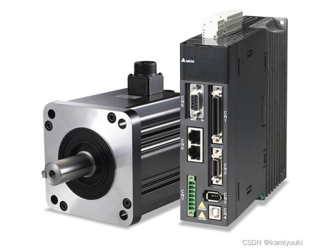
这里使用的伺服驱动器是台达的A2,使用差分信号驱动模式,实测stm32的3.3V电压可以驱动。

数据解读
stm32f10x_it.c
//中断函数变量
static u8 i=0;									//i为数组接收计数
static u8 j=0;									//j为取数据计数
char uctemp[8] = {0};						//uctemp为接收数组,因为uart接收只能一个字节一个字节的接收
char x_temp[8] = {0};						//x_temp为x轴偏移量存储数组
char y_temp[8] = {0};						//y_temp为y轴偏移量存储数组
extern volatile int x_bais;					//x为x轴偏移量
extern volatile int y_bais;					//y为y轴偏移量
extern volatile int target;					//y为y轴偏移量
extern volatile int receive;				//数据接收flag

extern volatile int Rotation_angle;
extern volatile int Limit_angle;
首先判断是否存在目标,如果不存在则不启动电机,同时亮红灯表示;
检测到目标则亮绿灯,同时可以启动电机,并判断出x轴y轴偏移误差,将char转化为int。
atoi(‘124e’)= 124;最后的‘e’会被忽略掉。
void DEBUG_USART_IRQHandler(void)										//每次中断都会调用中断函数
{
	u8 k=0;																//k为循环计数
	if(USART_GetITStatus(DEBUG_USARTx,USART_IT_RXNE)!=RESET)			//USART_IT_RXNE为接收中断标志位
	{
		receive = 3;												//是否接收到传输的数据
		uctemp[i] = USART_ReceiveData(DEBUG_USARTx);								//一位一位的接收
		j=i;
		if((uctemp[0] != '#'&&uctemp[0] != '$')||uctemp[i]=='e') i=0;		//判断数据报头报尾,当数据接收完毕的时i归0


		if(uctemp[0] == 'N')											//判断是否检测到目标,用target和LED作为检测结果展示
		{
			target=0;
			LED2_OFF;
			LED1_ON;
			x_bais = 0;
			y_bais = 0;
		}
		else if((uctemp[0] == '#') &&(uctemp[j] == 'e'))				//判断X偏移量
		{
			target=1;
			LED1_OFF;
			LED2_ON;
			for(k=0;k<j;k++){
			x_temp[k] = uctemp[k+1];
			}
			x_bais = atoi(x_temp);										//char转int

		}
		else if((uctemp[0] == '$') &&(uctemp[j] == 'e'))				//判断y偏移量
		{
			target=1;
			LED1_OFF;
			LED2_ON;
			for(k=0;k<j;k++){
			y_temp[k] = uctemp[k+1];
			}
			y_bais = atoi(y_temp);

		}else{i++;}

	}
}
电机控制
驱动伺服电机需要使用pwm波,我采用通用定时器产生PWM波,同时为了精确限位,使用另一个从定时器统计产生的脉冲数量。
因为伺服驱动器是通过脉冲数量来驱动电机运行的,本文设置的3600脉冲转一转,则转一度需要10脉冲
timer.c
#include "stm32f10x.h"
#include "timer.h"

/***************
主定时器配置函数
period:PWM周期
prescaler:预分频系数
pulse:占空比控制变量 也就是PWM有效电平的宽度
PWM输出IO为GPIOC_7
完全重映射至 TIM3_CH2
***************/

void Master_TIM(u16 period,u16 prescaler,u16 pulse)
{
	GPIO_InitTypeDef GPIO_InitStructure;

	// 输出比较通道2 GPIO 初始化
	RCC_APB2PeriphClockCmd(RCC_APB2Periph_GPIOA, ENABLE);
  GPIO_InitStructure.GPIO_Pin =  GPIO_Pin_7;
  GPIO_InitStructure.GPIO_Mode = GPIO_Mode_AF_PP;
  GPIO_InitStructure.GPIO_Speed = GPIO_Speed_50MHz;
  GPIO_Init(GPIOA, &GPIO_InitStructure);

	RCC_APB1PeriphClockCmd(RCC_APB1Periph_TIM3,ENABLE);

/*--------------------时基结构体初始化-------------------------*/
	// 配置周期,这里配置为100K

  TIM_TimeBaseInitTypeDef  TIM_TimeBaseStructure;
	// 自动重装载寄存器的值,累计TIM_Period+1个频率后产生一个更新或者中断
	TIM_TimeBaseStructure.TIM_Period=period;
	// 驱动CNT计数器的时钟 = Fck_int/(psc+1)
	TIM_TimeBaseStructure.TIM_Prescaler= prescaler;
	// 时钟分频因子 ,配置死区时间时需要用到
	TIM_TimeBaseStructure.TIM_ClockDivision=TIM_CKD_DIV1;
	// 计数器计数模式,设置为向上计数
	TIM_TimeBaseStructure.TIM_CounterMode=TIM_CounterMode_Up;
	// 重复计数器的值,没用到不用管
	TIM_TimeBaseStructure.TIM_RepetitionCounter=0;
	// 初始化定时器
	TIM_TimeBaseInit(TIM3, &TIM_TimeBaseStructure);

	/*--------------------输出比较结构体初始化-------------------*/

	TIM_OCInitTypeDef  TIM_OCInitStructure;
	// 配置为PWM模式1
	TIM_OCInitStructure.TIM_OCMode = TIM_OCMode_PWM1;
	// 输出使能
	TIM_OCInitStructure.TIM_OutputState = TIM_OutputState_Enable;
	// 输出通道电平极性配置
	TIM_OCInitStructure.TIM_OCPolarity = TIM_OCPolarity_High;

	// 输出比较通道 2
	TIM_OCInitStructure.TIM_Pulse = pulse;
	TIM_OC2Init(TIM3, &TIM_OCInitStructure);
	TIM_OC2PreloadConfig(TIM3, TIM_OCPreload_Enable);

	// 使能计数器
	TIM_Cmd(TIM3, DISABLE);

  TIM_SelectMasterSlaveMode(TIM3,TIM_MasterSlaveMode_Enable);  //TIM3选择使能主从模式主定时器
  TIM_SelectOutputTrigger(TIM3,TIM_TRGOSource_Update);         //TIM3选择更新事件作为trgo触发源,触发其他定时器
}


/************
从定时器配置函数
period:TIM4的溢出值 即设定的PWM脉冲数
***********/

void Slave_TIM(u16 period)
{

        NVIC_InitTypeDef NVIC_InitStructure;                         //中断初始化结构体
        TIM_TimeBaseInitTypeDef TIM_TimeBaseInitStructure;           //TIM4时基初始化结构体

        RCC_APB1PeriphClockCmd(RCC_APB1Periph_TIM4,ENABLE);          //使能TIM4时钟

        /********
        初始化TIM4时基
        设定所需PWM脉冲数
        ********/

        TIM_TimeBaseInitStructure.TIM_ClockDivision=TIM_CKD_DIV1;    //时钟不分频即直接使用
                                                                 //TIM3脉冲
        TIM_TimeBaseInitStructure.TIM_CounterMode=TIM_CounterMode_Up;
        TIM_TimeBaseInitStructure.TIM_Period=period;
        TIM_TimeBaseInitStructure.TIM_Prescaler=0;                   //PWM不分频
        TIM_TimeBaseInitStructure.TIM_RepetitionCounter=0;
        TIM_TimeBaseInit(TIM4,&TIM_TimeBaseInitStructure);

        TIM_SelectSlaveMode(TIM4,TIM_SlaveMode_External1);           //TIM4选择从定时器模式

				TIM_SelectInputTrigger(TIM4,TIM_TS_ITR2);                    //TIM4选择内部触发来源为
                                                               //TIM3

        TIM_Cmd(TIM4,DISABLE);                                       //同样初始化中不使能TIM4

        /***************
        配置TIM4的中断
        利用TIM4计数溢出作为中断事件关闭TIM3
        可达到精确计数的目的
        ****************/
				NVIC_PriorityGroupConfig(NVIC_PriorityGroup_2);      //配置中断优先级

        NVIC_InitStructure.NVIC_IRQChannel=TIM4_IRQn;
        NVIC_InitStructure.NVIC_IRQChannelCmd=ENABLE;
        NVIC_InitStructure.NVIC_IRQChannelPreemptionPriority=2;
        NVIC_InitStructure.NVIC_IRQChannelSubPriority=2;
        NVIC_Init(&NVIC_InitStructure);

        TIM_ITConfig(TIM4,TIM_IT_Update,ENABLE);                    //TIM4中断触发事件为update

}

/*************
方向控制IO配置函数
GPIOE_5
高电平顺时针
低电平逆时针
*************/

void DIR_Crl(void)
{

        GPIO_InitTypeDef GPIO_InitStructure;

        RCC_APB2PeriphClockCmd(RCC_APB2Periph_GPIOE,ENABLE);

        GPIO_InitStructure.GPIO_Mode=GPIO_Mode_Out_PP;
        GPIO_InitStructure.GPIO_Pin=GPIO_Pin_9;
        GPIO_InitStructure.GPIO_Speed=GPIO_Speed_50MHz;
        GPIO_Init(GPIOE,&GPIO_InitStructure);
}
主函数
主函数主要是控制电机,因为x轴y轴的控制方式基本一样,我这里只写了一个电机的控制,需要两个的可以复制粘贴,稍微修改就可以了。
#include "stm32f10x.h"
#include "bsp_usart.h"
#include <stdlib.h>
#include <stdio.h>
#include "bsp_led.h"
#include "systick.h"
#include "bsp_beep.h"
#include "timer.h"

volatile int x_bais;
volatile int y_bais;
volatile int target;
volatile int receive = 3;

volatile int Rotation_angle = 100;			//一秒多少角度
volatile int Limit_angle = 90;				//当前驱动器的角度,用来限制旋转角度
/**
  * @brief  主函数
  * @param  无
  * @retval 无
	//36号线为方向控制线,链接PE9,43号线为脉冲线,链接PA7(tim3 2通道),41和37接地
  */

int main(void)
{
	int Pulse_num = Rotation_angle*10;			//每秒多少脉冲(伺服驱动器设置3600脉冲一周,所以是10脉冲一度)
	int value_num = 100000/Pulse_num - 1;
	int Duty_cycle = 50;				//设置占空比,脉冲信号只要被检测到就可以了,不用太长的占空比(低电平占空比)
	int cycle_num = (Duty_cycle*value_num)/100;


  /*初始化USART 配置模式为 115200 8-N-1,中断接收*/
  USART_Config();
	initSysTick();
	LED_GPIO_Config();
	BEEP_GPIO_Config();																//BEEP作为通讯中断警报

	Usart_SendString( DEBUG_USARTx,"串口通讯调试实验\n");

	Master_TIM(value_num,719,cycle_num); 							//720分频,主定时器设置每秒产生脉冲数和占空比
	DIR_Crl();                                        //电机方向接口初始化
 	Motor_CW;                                         //控制电机顺时针旋转
 	Slave_TIM(20);                                    //从定时器设定脉冲数为20,小数量便于验证
	delay_ms(10);
 	TIM_Cmd(TIM4,ENABLE);


  while(1)
	{
		if(receive == 0)
		{
			TIM_Cmd(TIM3,DISABLE);
			BEEP(1);
			delay_ms(1000);
			printf("长时间未接收到数据,系统异常!!!\n");
		}
		else{
			BEEP(0);
			receive--;
//			delay_ms(1000);
//			printf("target:%s ,x=%d,y=%d\r",(target==1?"YES":"NO"),x_bais,y_bais);
			if(target == 1)
			{
				if(x_bais > 5 && Limit_angle <= 150)
				{
					Motor_CW;
					TIM_Cmd(TIM3,ENABLE);
				}
				else if(x_bais < -5 && Limit_angle >= 50)
				{
					Motor_CCW;
					TIM_Cmd(TIM3,ENABLE);
				}else TIM_Cmd(TIM3,DISABLE);
			}else TIM_Cmd(TIM3,DISABLE);
		}

	}
}
电机加减速
我目前的实验没有用到加减速,但是可以作为全局变量放进去自动控制。
暂时使用的是外部中断
//外部中断
  #include "bsp_exti.h"

//配置中断优先级   static 静态声明,只能被声明过的文件调用
static void EXTI_NVIC_Config(void)
{
	NVIC_InitTypeDef NVIC_InitStructure1;
	NVIC_InitTypeDef NVIC_InitStructure2;

	NVIC_PriorityGroupConfig(NVIC_PriorityGroup_1);
	NVIC_InitStructure1.NVIC_IRQChannel = EXTI0_IRQn;   //对应中断函数
	NVIC_InitStructure1.NVIC_IRQChannelPreemptionPriority = 1;
	NVIC_InitStructure1.NVIC_IRQChannelSubPriority = 1;
	NVIC_InitStructure1.NVIC_IRQChannelCmd = ENABLE;
	NVIC_Init( &NVIC_InitStructure1);

	NVIC_PriorityGroupConfig(NVIC_PriorityGroup_1);   		//配置中断优先级组号
	NVIC_InitStructure2.NVIC_IRQChannel = EXTI15_10_IRQn;	//对应中断函数
	NVIC_InitStructure2.NVIC_IRQChannelPreemptionPriority = 1;
	NVIC_InitStructure2.NVIC_IRQChannelSubPriority = 1;
	NVIC_InitStructure2.NVIC_IRQChannelCmd = ENABLE;
	NVIC_Init( &NVIC_InitStructure2);
}

void EXTI_KEY_Config(void)
{
	GPIO_InitTypeDef GPIO_InitStructure;
	EXTI_InitTypeDef EXTI_InitStructure1;
	EXTI_InitTypeDef EXTI_InitStructure2;

	EXTI_NVIC_Config();   //配置中断优先级

	/*开启按键端口的时钟*/
	RCC_APB2PeriphClockCmd(KEY1_GPIO_CLK|KEY2_GPIO_CLK|RCC_APB2Periph_AFIO,ENABLE);

	//选择按键的引脚
	GPIO_InitStructure.GPIO_Pin = KEY1_GPIO_PIN;
	// 设置按键的引脚为浮空输入
	GPIO_InitStructure.GPIO_Mode = GPIO_Mode_IN_FLOATING;
	//使用结构体初始化按键
	GPIO_Init(KEY1_GPIO_PORT, &GPIO_InitStructure);

	GPIO_InitStructure.GPIO_Pin = KEY2_GPIO_PIN;
	GPIO_InitStructure.GPIO_Mode = GPIO_Mode_IN_FLOATING;
	GPIO_Init(KEY2_GPIO_PORT, &GPIO_InitStructure);

	//初始化EXTI
	GPIO_EXTILineConfig(GPIO_PortSourceGPIOA, GPIO_PinSource0);
	EXTI_InitStructure1.EXTI_Line = EXTI_Line0;
	EXTI_InitStructure1.EXTI_Mode = EXTI_Mode_Interrupt;
	EXTI_InitStructure1.EXTI_Trigger = EXTI_Trigger_Rising;
	EXTI_InitStructure1.EXTI_LineCmd = ENABLE;
	EXTI_Init( &EXTI_InitStructure1);

	//初始化EXT15_10
	GPIO_EXTILineConfig(GPIO_PortSourceGPIOC, GPIO_PinSource13);
	EXTI_InitStructure2.EXTI_Line = EXTI_Line13;
	EXTI_InitStructure2.EXTI_Mode = EXTI_Mode_Interrupt;
	EXTI_InitStructure2.EXTI_Trigger = EXTI_Trigger_Rising;
	EXTI_InitStructure2.EXTI_LineCmd = ENABLE;
	EXTI_Init( &EXTI_InitStructure2);

}
//中断函数
void EXTI0_IRQHandler(void)
{
  if(EXTI_GetITStatus( EXTI_Line0)!= RESET)
  {
    Rotation_angle+=10;
		printf("Rotation_angle = %d\r\n",Rotation_angle);
  }
  EXTI_ClearITPendingBit(EXTI_Line0);
}

void EXTI15_10_IRQHandler(void)
{
  if(EXTI_GetITStatus( EXTI_Line13)!= RESET)
  {
    Rotation_angle-=10;
		printf("Rotation_angle = %d\r\n",Rotation_angle);
  }
  EXTI_ClearITPendingBit(EXTI_Line13);
}
硬件图:
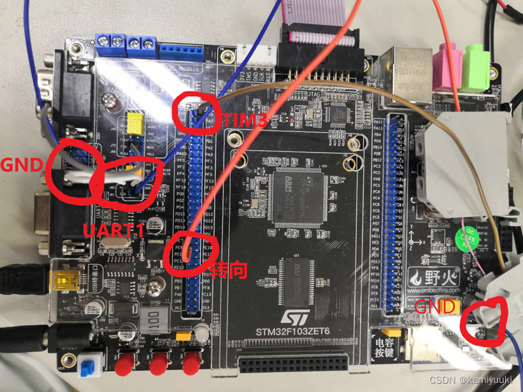
STM32 :
伺服驱动器 41号,37号接stm32的GND
43号连接PA7(TIM3的channel2 PWM输出通道)
36号连接PE9(转动方向控制)
Stm32的PA9链接串口RX(用于发送到上位机观看数据)
切记,伺服驱动器的接地工作一定要做好,不然会出现即使不上电或者不给信号电机依旧会转的情况。

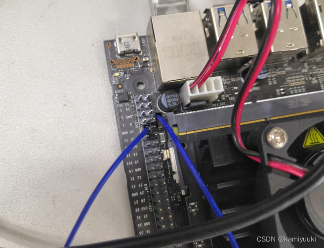
jetson nano:
硬件连线如图,8号(TX)接PA10(UART1_RX),10号(RX)可以用来接收stm32的信息,PA9(UART1_TX)

总结
以上就是整个程序了,除了一些小细节外其他的应该都比较清楚,欢迎有想法或者有疑问的同学提问,如果有错误也欢迎指正!