前言
时不可以苟遇,道不可以虚行。
一、准备
1.软件
- CLion-2020:百度网盘提取链接放在文章最后。
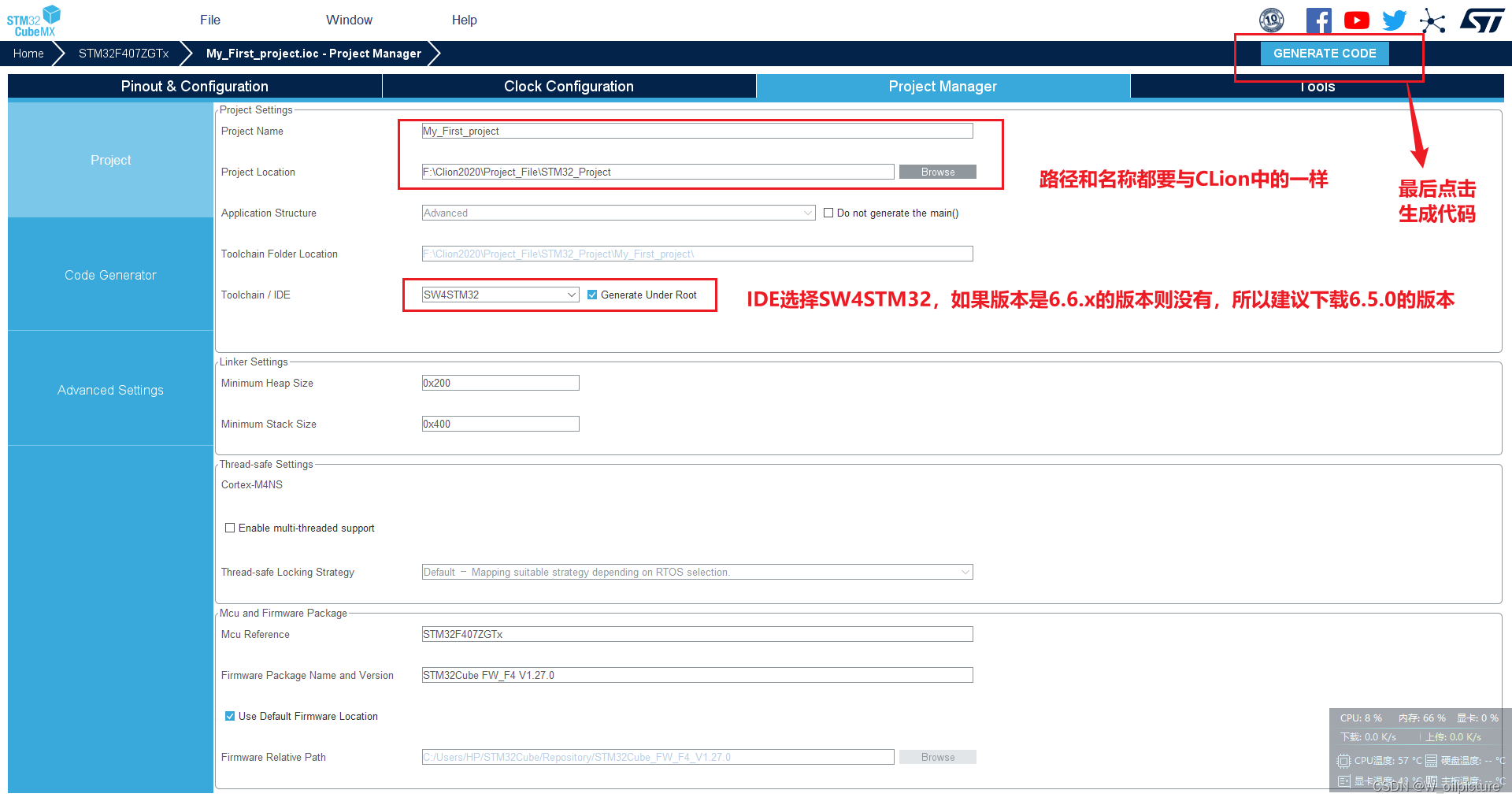
- STM32CubeMX:使用 6.5.0 版本的,不要使用最新版本的 CubeMX,不然没有 SW4STM32 的 IDE 选项,自行去官网下载即可。
- MinGW:Clion需要使用MinGW环境来配置工具链。
- OpenOCD:用于对STM32进行下载仿真的工具,是一个开源软件包。
- arm-none-eabi-gcc
2.硬件
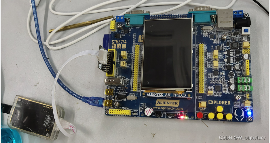
- 开发板:正点原子的
STM32F407ZGT6的探索者开发板 - 下载器:
DAP-link下载器(不同下载器均可)
二、软件安装
1.MinGW
- 去MinGW主页下载最新版本的MinGW: Minimalist GNU for Windows
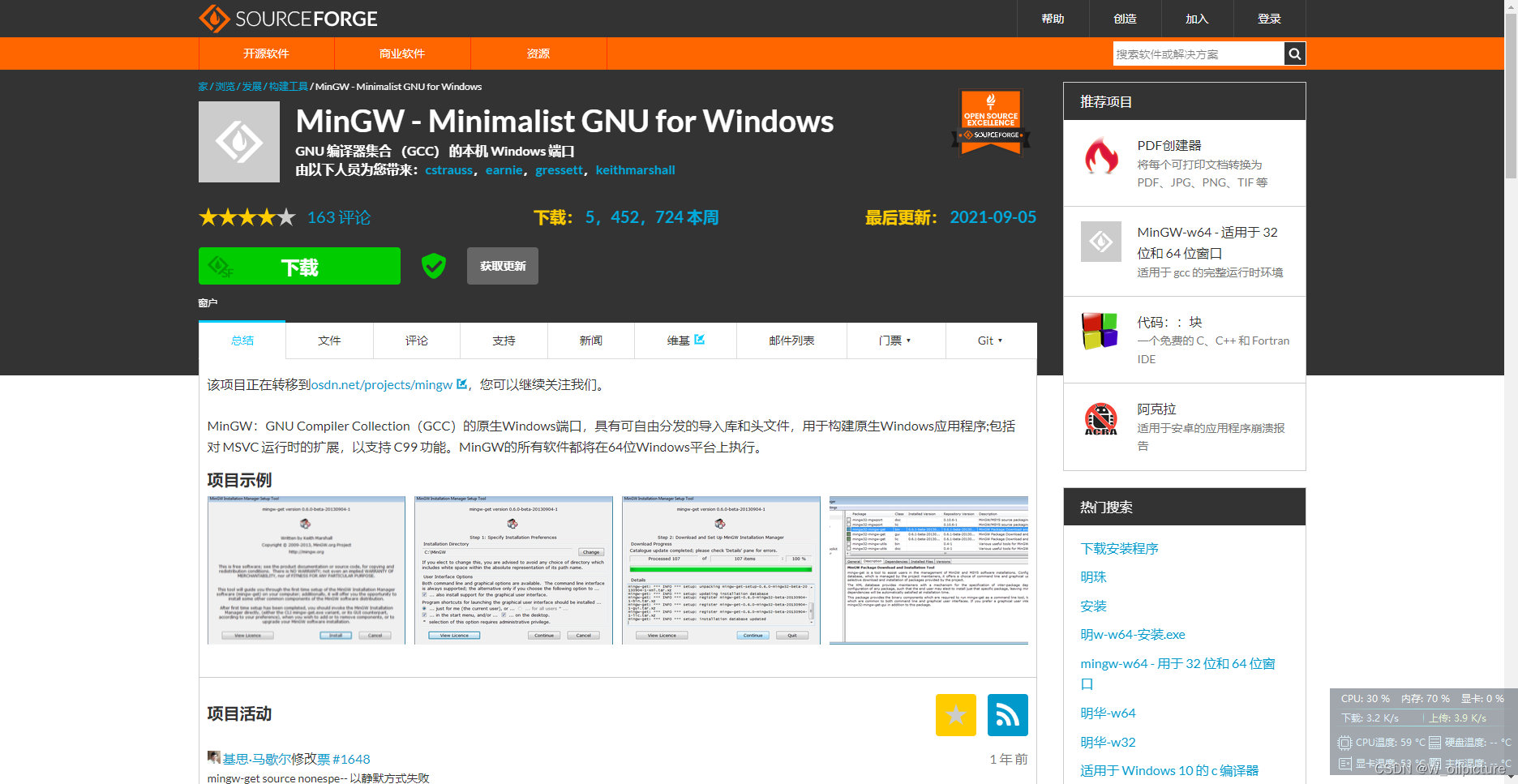
- 下载完成后,双击
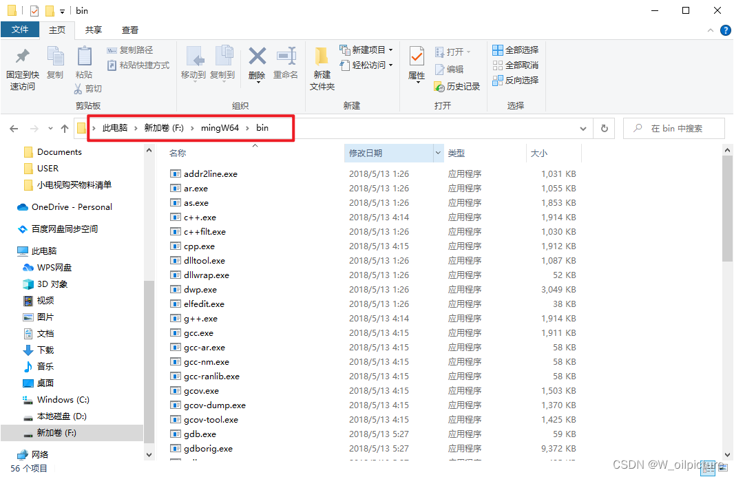
exe进行安装,安装路径不要存在空格和中文; - 复制安装路径:
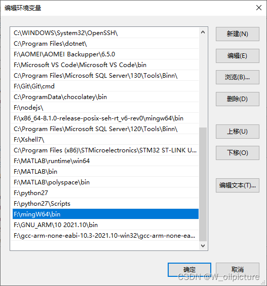
- 配置系统的环境变量,在
Path环境变量里面添加一条,指向MinGW的bin文件夹:
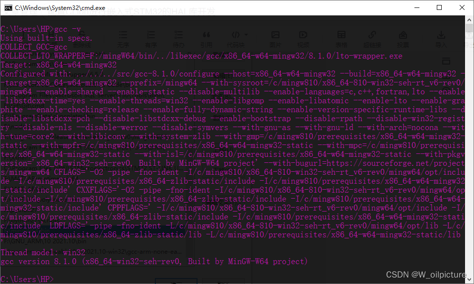
- 最后检测是否安装成功,重启电脑,按键 Ctrl + R 打开运行窗口,唤出 cmd,输入:
gcc -v,如果出现版本信息,则安装成功。
2.arm-none-eabi-gcc
-
下载网址:https://developer.arm.com/open-source/gnu-toolchain/gnu-rm/downloads,选择 ZIP 压缩包形式下载
-
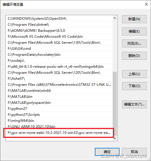
然后解压到电脑中,并把安装目录下的 bin 文件添加到环境变量中:
-
然后 重启 使环境变量生效后,在命令行中输入测试语句:(出现版本信息,则表示安装成功)
arm-none-eabi-gcc -v

三、CLion的配置
-
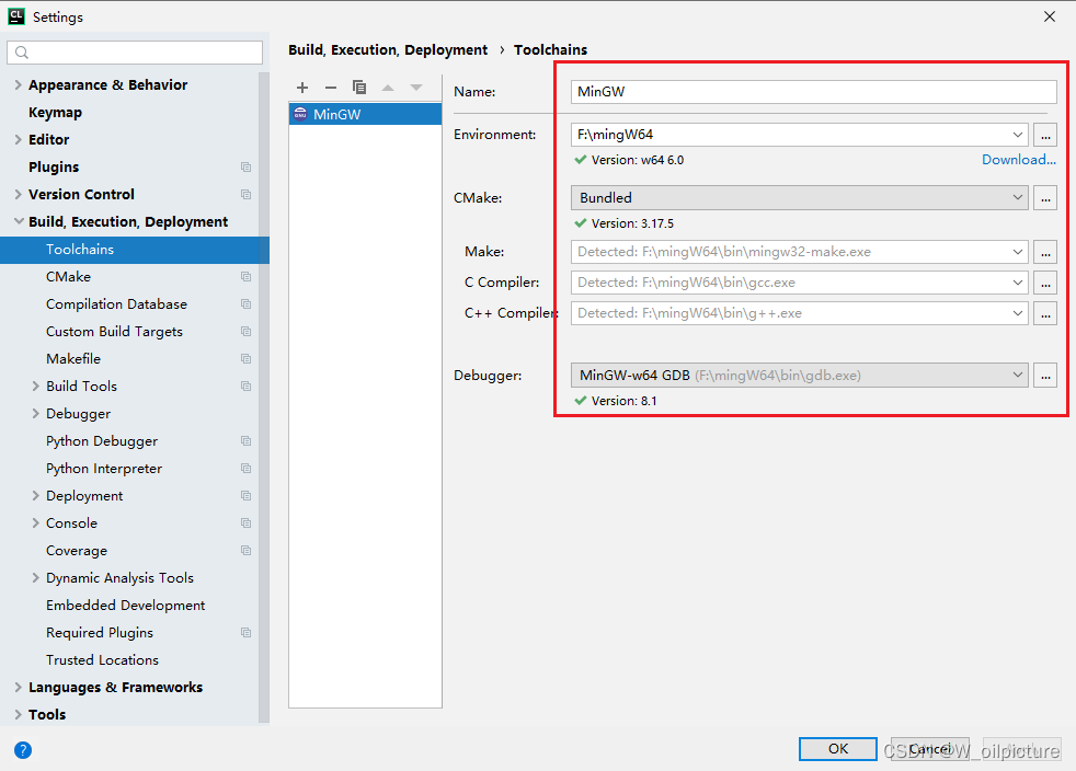
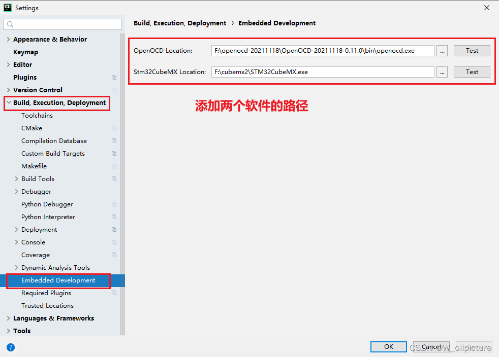
配置 MinGW 的编译环境:(点击:
file -> settings -> Build,Execution,Deployment,添加 MinGW 的路径)
-
这样就完成的环境配置,下面可以开始创建 STM32 项目。
四、创建CubeMX工程
-
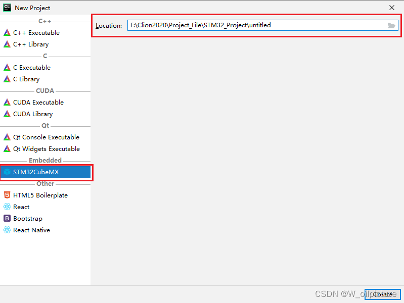
在 CLion 中选择 file -> New Project 创建STM32CubeMX 工程:
-
点击创建后,会出现一个 .ios 文件,点击链接可以进入 CubeMX 进行配置;
-
然后就是配置 CubeMX 的过程,最后生成代码的时候:
-
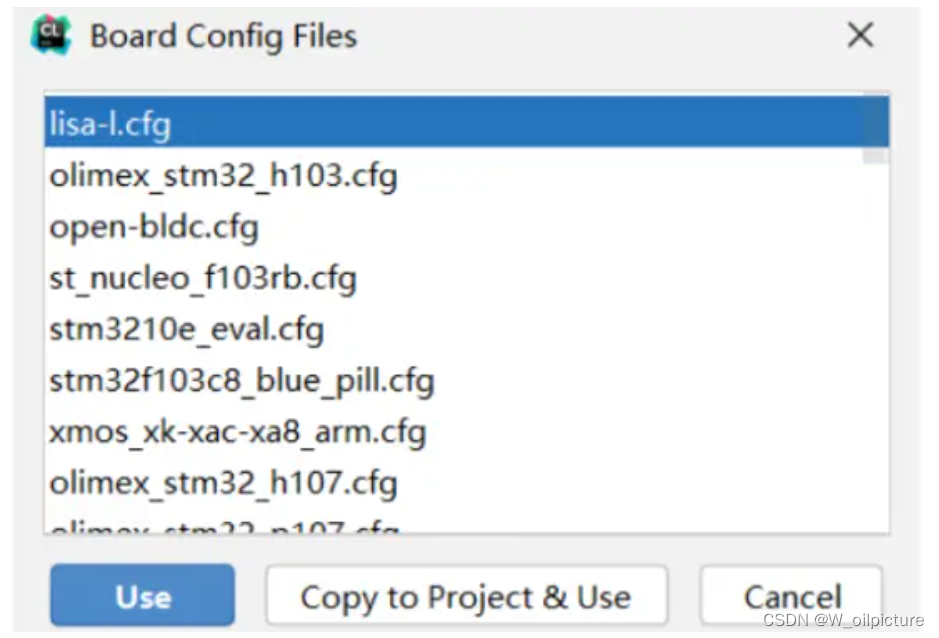
第一次设置完后
CLion中会出现一个板卡选择窗口,可以取消不选:
-
板卡的选择可以在 OpenOCD 中进行选择,可以自己进行配置文件的选择。
五、编译工程
- 在 CLion 的界面的右上角可以看到:

- 点击编译按钮进行工程的编译:(成功生成用于烧写的 .bin 和 .hex 文件)

烧录程序
- 我们需要选择我们烧录的方式,使用的下载器(J-Link、ST-Link、CMSIS-DAPLink等)
- 在我们的工程文件中新建一个:
DAPLink.cfg的文件
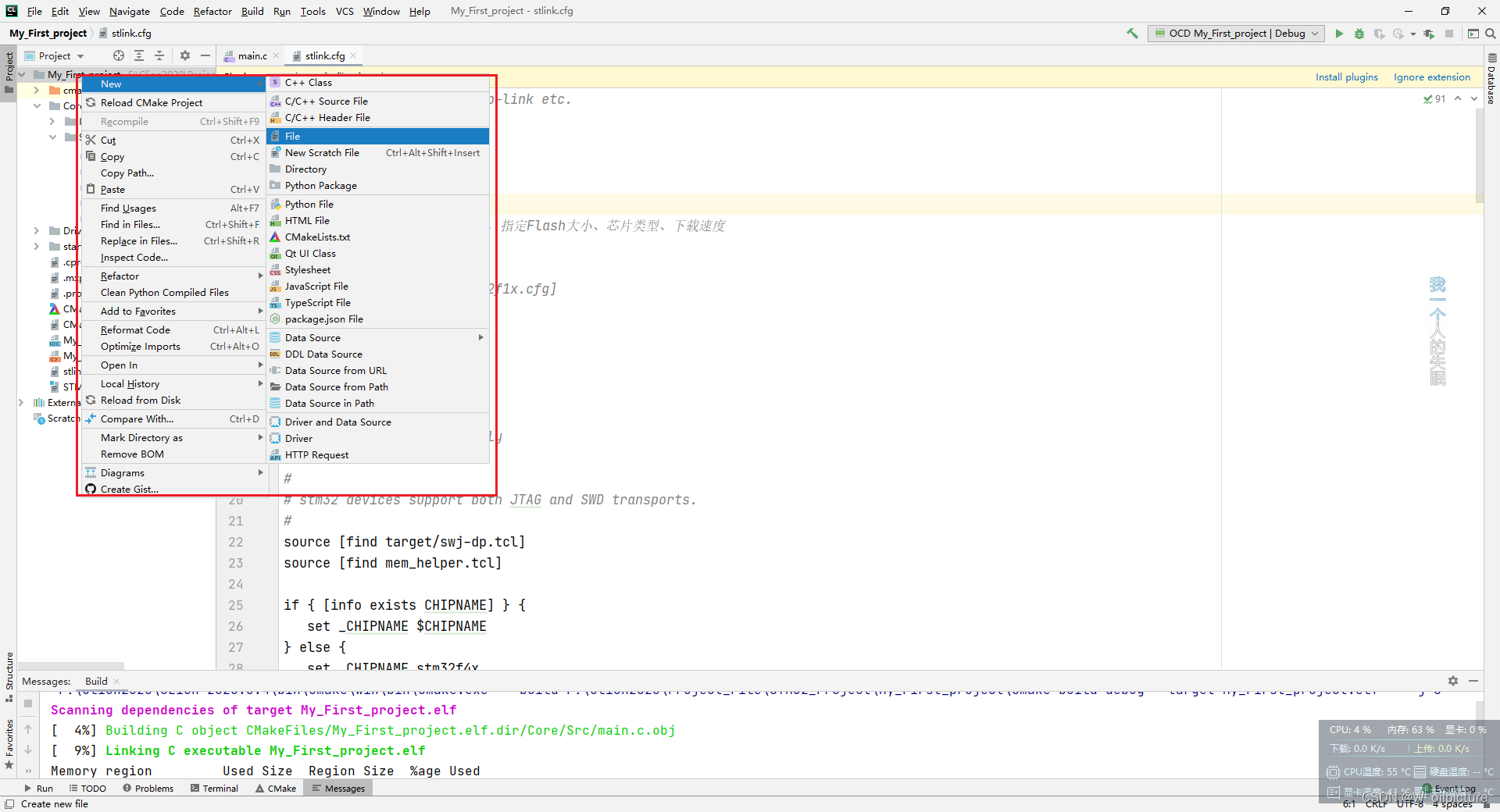
- 我这里选择的是:正点原子的 STM32F407ZGT6 的探索者开发板,使用的烧录方式是:
DAPlink,新建的 .cfg 文件内容如下:
# choose st-link/j-link/dap-link etc.

# 前两行设置仿真器的类型和接口
adapter driver cmsis-dap
transport select swd

# 0x10000 = 64K Flash Size,指定Flash大小、芯片类型、下载速度
;
; set FLASH_SIZE 0x20000
; source [find target/stm32f1x.cfg]
;
;
;
; # download speed = 10MHz
;
; adapter speed 10000
# script for stm32f4x family

#
# stm32 devices support both JTAG and SWD transports.
#
source [find target/swj-dp.tcl]
source [find mem_helper.tcl]

if { [info exists CHIPNAME] } {
   set _CHIPNAME $CHIPNAME
} else {
   set _CHIPNAME stm32f4x
}

set _ENDIAN little

# Work-area is a space in RAM used for flash programming
# By default use 32kB (Available RAM in smallest device STM32F410)
if { [info exists WORKAREASIZE] } {
   set _WORKAREASIZE $WORKAREASIZE
} else {
   set _WORKAREASIZE 0x8000
}

#jtag scan chain
if { [info exists CPUTAPID] } {
   set _CPUTAPID $CPUTAPID
} else {
   if { [using_jtag] } {
      # See STM Document RM0090
      # Section 38.6.3 - corresponds to Cortex-M4 r0p1
      set _CPUTAPID 0x4ba00477
   } {
      set _CPUTAPID 0x2ba01477
   }
}

swj_newdap $_CHIPNAME cpu -irlen 4 -ircapture 0x1 -irmask 0xf -expected-id $_CPUTAPID
dap create $_CHIPNAME.dap -chain-position $_CHIPNAME.cpu

tpiu create $_CHIPNAME.tpiu -dap $_CHIPNAME.dap -ap-num 0 -baseaddr 0xE0040000

if {[using_jtag]} {
   jtag newtap $_CHIPNAME bs -irlen 5
}

set _TARGETNAME $_CHIPNAME.cpu
target create $_TARGETNAME cortex_m -endian $_ENDIAN -dap $_CHIPNAME.dap

$_TARGETNAME configure -work-area-phys 0x20000000 -work-area-size $_WORKAREASIZE -work-area-backup 0

set _FLASHNAME $_CHIPNAME.flash
flash bank $_FLASHNAME stm32f2x 0 0 0 0 $_TARGETNAME

flash bank $_CHIPNAME.otp stm32f2x 0x1fff7800 0 0 0 $_TARGETNAME

if { [info exists QUADSPI] && $QUADSPI } {
   set a [llength [flash list]]
   set _QSPINAME $_CHIPNAME.qspi
   flash bank $_QSPINAME stmqspi 0x90000000 0 0 0 $_TARGETNAME 0xA0001000
}

# JTAG speed should be <= F_CPU/6. F_CPU after reset is 16MHz, so use F_JTAG = 2MHz
#
# Since we may be running of an RC oscilator, we crank down the speed a
# bit more to be on the safe side. Perhaps superstition, but if are
# running off a crystal, we can run closer to the limit. Note
# that there can be a pretty wide band where things are more or less stable.
adapter speed 2000

adapter srst delay 100
if {[using_jtag]} {
 jtag_ntrst_delay 100
}

reset_config srst_nogate

if {![using_hla]} {
   # if srst is not fitted use SYSRESETREQ to
   # perform a soft reset
   cortex_m reset_config sysresetreq
}

$_TARGETNAME configure -event examine-end {
	# Enable debug during low power modes (uses more power)
	# DBGMCU_CR |= DBG_STANDBY | DBG_STOP | DBG_SLEEP
	mmw 0xE0042004 0x00000007 0

	# Stop watchdog counters during halt
	# DBGMCU_APB1_FZ |= DBG_IWDG_STOP | DBG_WWDG_STOP
	mmw 0xE0042008 0x00001800 0
}

proc proc_post_enable {_chipname} {
	targets $_chipname.cpu

	if { [$_chipname.tpiu cget -protocol] eq "sync" } {
		switch [$_chipname.tpiu cget -port-width] {
			1 {
				mmw 0xE0042004 0x00000060 0x000000c0
				mmw 0x40021020 0x00000000 0x0000ff00
				mmw 0x40021000 0x000000a0 0x000000f0
				mmw 0x40021008 0x000000f0 0x00000000
			  }
			2 {
				mmw 0xE0042004 0x000000a0 0x000000c0
				mmw 0x40021020 0x00000000 0x000fff00
				mmw 0x40021000 0x000002a0 0x000003f0
				mmw 0x40021008 0x000003f0 0x00000000
			  }
			4 {
				mmw 0xE0042004 0x000000e0 0x000000c0
				mmw 0x40021020 0x00000000 0x0fffff00
				mmw 0x40021000 0x00002aa0 0x00003ff0
				mmw 0x40021008 0x00003ff0 0x00000000
			  }
		}
	} else {
		mmw 0xE0042004 0x00000020 0x000000c0
	}
}

$_CHIPNAME.tpiu configure -event post-enable "proc_post_enable $_CHIPNAME"

$_TARGETNAME configure -event reset-init {
	# Configure PLL to boost clock to HSI x 4 (64 MHz)
	mww 0x40023804 0x08012008   ;# RCC_PLLCFGR 16 Mhz /8 (M) * 128 (N) /4(P)
	mww 0x40023C00 0x00000102   ;# FLASH_ACR = PRFTBE | 2(Latency)
	mmw 0x40023800 0x01000000 0 ;# RCC_CR |= PLLON
	sleep 10                    ;# Wait for PLL to lock
	mmw 0x40023808 0x00001000 0 ;# RCC_CFGR |= RCC_CFGR_PPRE1_DIV2
	mmw 0x40023808 0x00000002 0 ;# RCC_CFGR |= RCC_CFGR_SW_PLL

	# Boost JTAG frequency
	adapter speed 8000
}

$_TARGETNAME configure -event reset-start {
	# Reduce speed since CPU speed will slow down to 16MHz with the reset
	adapter speed 2000
}
-
我是在OpenOCD 中找到相应的板卡的文件直接复制的内容。分别可设置:仿真器的类型和接口、Flash的大小、芯片类型、下载速度
-
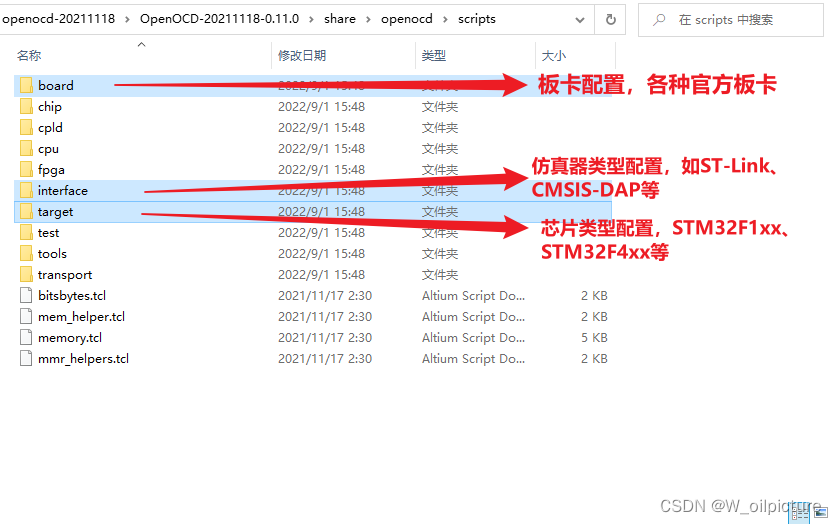
在我们安装的
OpenOCD的路径下,进入:share -> openocd -> scripts,看到以下文件:
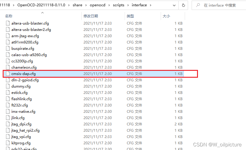
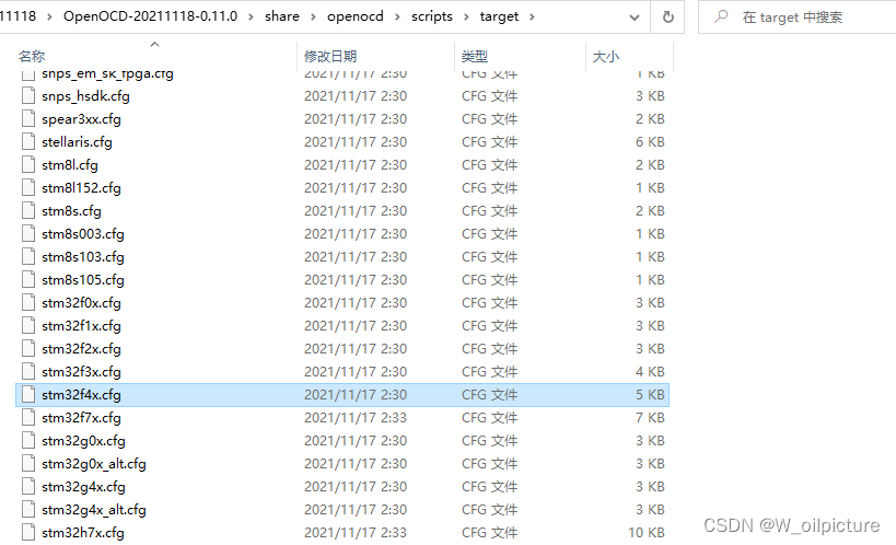
-
把里面的内容复制到我们新建的文件中,然后在 CLion 中添加路径:
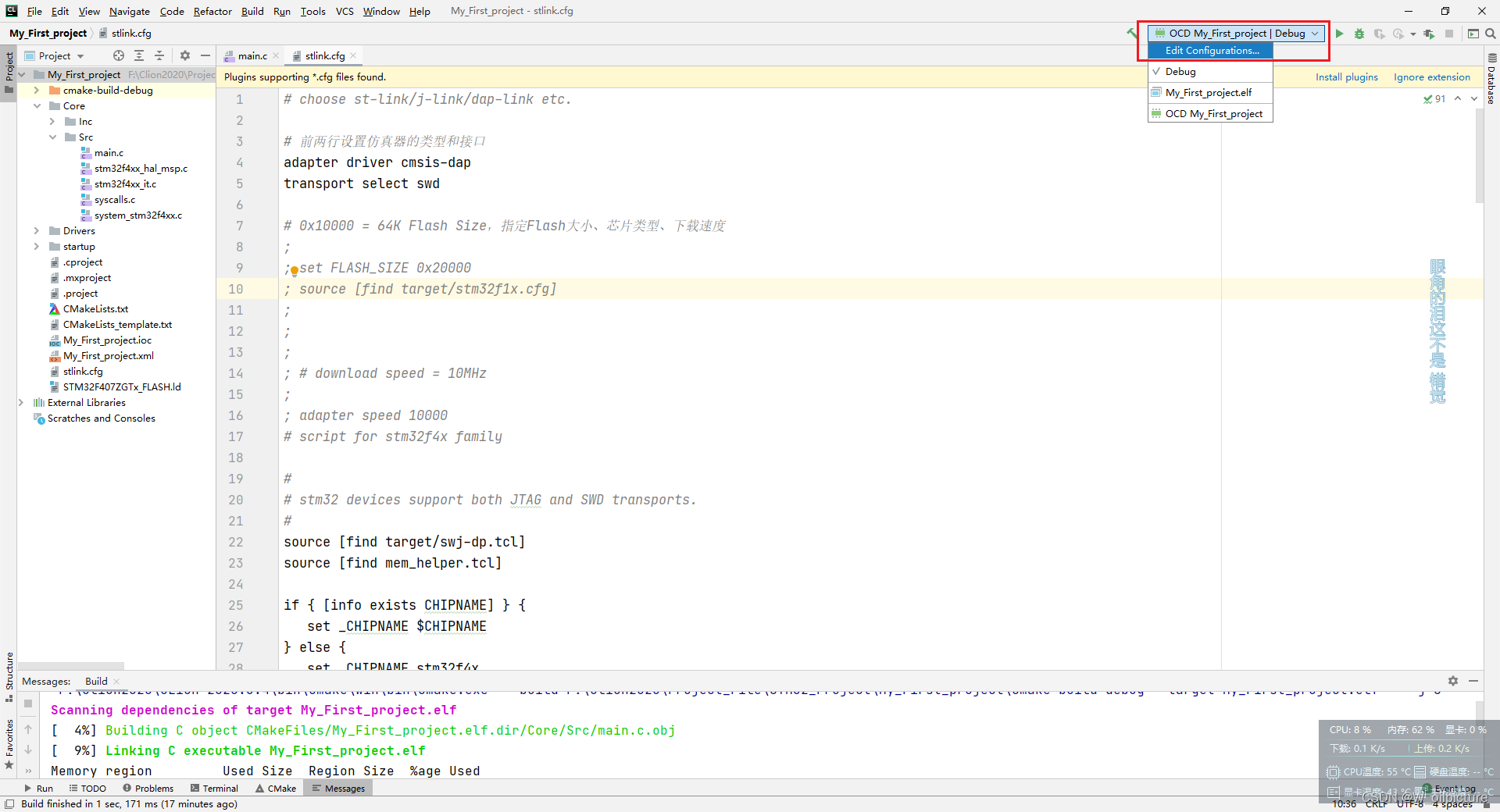
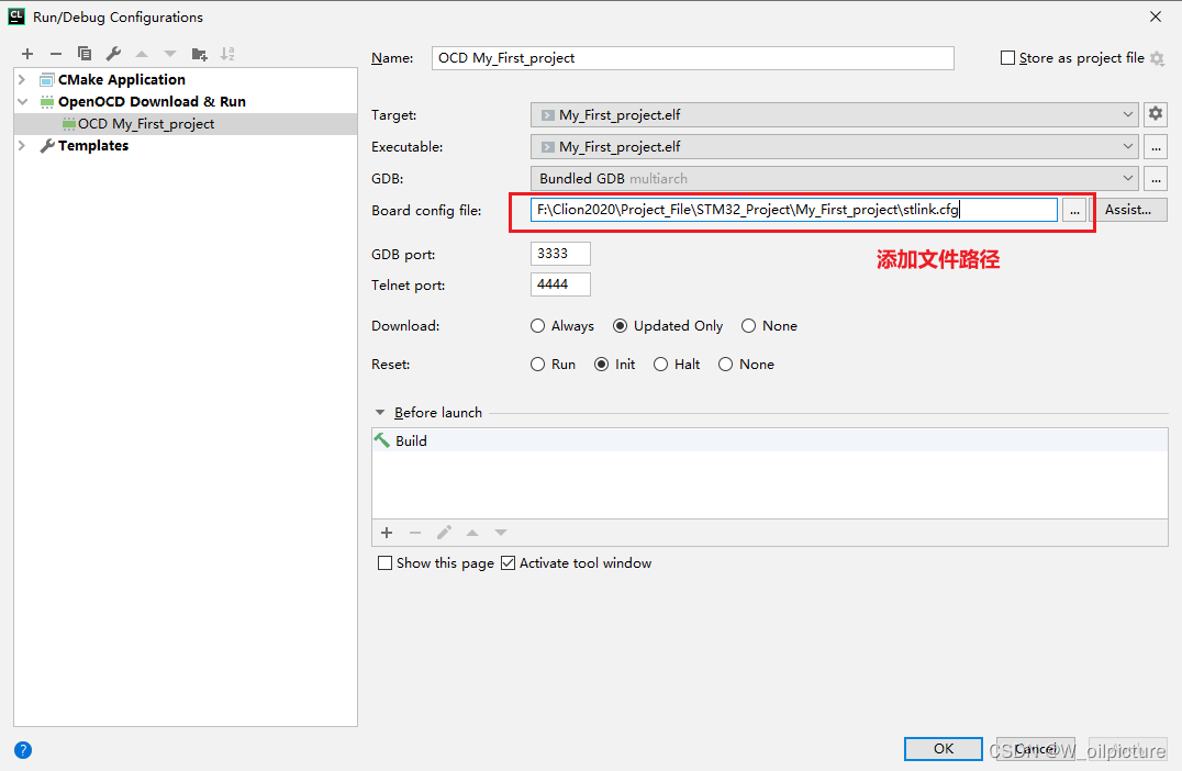
-
完成上述步骤后就可进行 下载 :(出现下列信息,下载成功)

-
上述就是对配置CLion进行嵌入式STM32的HAL库开发的分享。
-
CLion 的百度网盘连接:链接: https://pan.baidu.com/s/1NrGGM0gjb-4g9nwftYXgjw 提取码: hnyp。