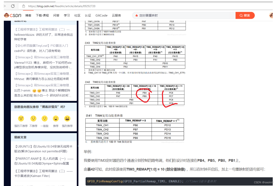
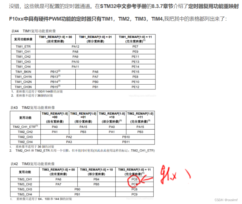
注意需要进行定时器的引脚复用,不然不得。


#include "al422b.h"
#include "usart.h"
u8 TIM3_CAPTURE_STA=0;   //输入捕获状态
u16 TIM3_CAPTURE_VAL;    //输入捕获值


u8 TIM4_CAPTURE_STA=0;   //输入捕获状态
u16 TIM4_CAPTURE_VAL;    //输入捕获值


void AL422B_wen_Init(u16 arr,u16 psc)
{


    GPIO_InitTypeDef GPIO_InitStructure;                        //定义GPIO结构体
    NVIC_InitTypeDef NVIC_InitStructure;                        //定义中断优先级结构体
    TIM_TimeBaseInitTypeDef TIM_TimeBaseStructure;              //定义TIM2定时器结构体
    TIM_ICInitTypeDef TIM_ICInitStructure;                      //定义输入捕获结构体

    NVIC_PriorityGroupConfig(NVIC_PriorityGroup_0);
	//配置中断优先级分组GPIO_FullRemap_TIM3  GPIO_PartialRemap_TIM3
	   GPIO_PinRemapConfig(GPIO_FullRemap_TIM3, ENABLE); //Timer3部分重映射
    RCC_APB1PeriphClockCmd(RCC_APB1Periph_TIM3,ENABLE);

	//使能TIM2时钟
    RCC_APB2PeriphClockCmd(RCC_APB2Periph_GPIOC,ENABLE);        //使能GPIOA时钟

    GPIO_InitStructure.GPIO_Pin = GPIO_Pin_8;                   //PA0
    GPIO_InitStructure.GPIO_Mode = GPIO_Mode_IPD;               //下拉输入模式
		GPIO_InitStructure.GPIO_Speed = GPIO_Speed_50MHz;
    GPIO_Init(GPIOC,&GPIO_InitStructure);

    TIM_TimeBaseStructure.TIM_Period = arr;                     //设置在下一个更新事件活动的自动装载寄存器周期的值
    TIM_TimeBaseStructure.TIM_Prescaler = psc;                  //设置用来作为TIMx时钟频率除数的预分频值
    TIM_TimeBaseStructure.TIM_ClockDivision = TIM_CKD_DIV1;     //设置时钟分割:TDTS = Tck_tim
    TIM_TimeBaseStructure.TIM_CounterMode = TIM_CounterMode_Up; //TIM向上计数
    TIM_TimeBaseInit(TIM3,&TIM_TimeBaseStructure);              //根据指定的参数初始化TIMx的时间基数单位

    TIM_ICInitStructure.TIM_Channel = TIM_Channel_3;                //选择输入端IC1映射到TI1上
    TIM_ICInitStructure.TIM_ICPolarity = TIM_ICPolarity_Rising;     //上升沿捕获
    TIM_ICInitStructure.TIM_ICSelection = TIM_ICSelection_DirectTI; //映射到TI1上
		//TIM_ICSelection_IndirectTI  TIM_ICSelection_DirectTI
    TIM_ICInitStructure.TIM_ICPrescaler = 0;           //配置输入分频,不分频
    TIM_ICInitStructure.TIM_ICFilter = 0x00;                        //IC1F=0000配置输入滤波器 不滤波
    TIM_ICInit(TIM3,&TIM_ICInitStructure);

    NVIC_InitStructure.NVIC_IRQChannel = TIM3_IRQn;               //TIM2中断源
    NVIC_InitStructure.NVIC_IRQChannelPreemptionPriority = 0;     //抢占优先级2级
    NVIC_InitStructure.NVIC_IRQChannelSubPriority =0;            //子优先级0级
    NVIC_InitStructure.NVIC_IRQChannelCmd = ENABLE;               //IRQ通道被使能
    NVIC_Init(&NVIC_InitStructure);          //初始化外设NVIC寄存器
    TIM_ClearITPendingBit(TIM3,TIM_IT_Update|TIM_IT_CC3);    //清除中断标志位

    TIM_ITConfig(TIM3,TIM_IT_Update|TIM_IT_CC3,ENABLE);           //允许更新中断CC3IE捕获中断
    TIM_Cmd(TIM3,ENABLE );                                        //使能定时器3

   // printf("dddd\r\n");
}


void TIM3_IRQHandler(void)            //TIM3中断服务函数
{
    if((TIM3_CAPTURE_STA & 0X80) == 0)   //还未成功捕获,最高位是捕获完成的标志位,
    {
        if((TIM_GetITStatus(TIM3,TIM_IT_Update) != RESET))
        {
					  //printf("1111\r\n");
            if(TIM3_CAPTURE_STA & 0X40)                   //已经捕获到高电平了
            {
                if((TIM3_CAPTURE_STA & 0X3F) == 0X3F)     //高电平太长了,设置一个最大值
                {
                    TIM3_CAPTURE_STA |= 0X80;             //标记成功捕获了一次
                    TIM3_CAPTURE_VAL = 0XFFFF;
								//	 printf("2222\r\n");
                }
                else TIM3_CAPTURE_STA++;//捕获状态加1
            }
        }


        if(TIM_GetITStatus(TIM3,TIM_IT_CC3) != RESET)   //捕获 1 发生捕获事件
        {
							// printf("3333\r\n");

            if(TIM3_CAPTURE_STA & 0X40)                 //捕获到一个下降沿
            {
                TIM3_CAPTURE_STA |= 0X80;               //标记成功捕获到一次上升沿
                TIM3_CAPTURE_VAL = TIM_GetCapture3(TIM3);
               TIM_OC3PolarityConfig(TIM3,TIM_ICPolarity_Rising);//CC1P=0 设置为上升沿捕获
            }
            else    //还未开始,第一次捕获上升沿
            {
                TIM3_CAPTURE_STA = 0;         //清空
                TIM3_CAPTURE_VAL = 0;

                TIM_SetCounter(TIM3,0);
                TIM3_CAPTURE_STA |= 0X40;     //标记捕获到了上升沿

               TIM_OC3PolarityConfig(TIM3,TIM_ICPolarity_Falling); //CC1P=1 设置为下降沿捕获
            }
						TIM_ClearFlag(TIM3, TIM_FLAG_CC3);   		                             //清除状态标志


        }
    }
    TIM_ClearITPendingBit(TIM3,TIM_IT_Update|TIM_IT_CC3);    //清除中断标志位
}

//Tim4 CH4 ,,PD15
void AL422B_sh_Init(u16 arr,u16 psc)
{
	GPIO_InitTypeDef GPIO_InitStructure;                        //定义GPIO结构体
    NVIC_InitTypeDef NVIC_InitStructure;                        //定义中断优先级结构体
    TIM_TimeBaseInitTypeDef TIM_TimeBaseStructure;              //定义TIM2定时器结构体
    TIM_ICInitTypeDef TIM_ICInitStructure;                      //定义输入捕获结构体

    NVIC_PriorityGroupConfig(NVIC_PriorityGroup_0);
	//配置中断优先级分组GPIO_FullRemap_TIM3  GPIO_PartialRemap_TIM3
	   GPIO_PinRemapConfig(GPIO_Remap_TIM4, ENABLE); //Timer3部分重映射
    RCC_APB1PeriphClockCmd(RCC_APB1Periph_TIM4,ENABLE);

	//使能TIM2时钟
    RCC_APB2PeriphClockCmd(RCC_APB2Periph_GPIOD,ENABLE);        //使能GPIOA时钟

    GPIO_InitStructure.GPIO_Pin = GPIO_Pin_15;                   //PA0
    GPIO_InitStructure.GPIO_Mode = GPIO_Mode_IPD;               //下拉输入模式
		GPIO_InitStructure.GPIO_Speed = GPIO_Speed_50MHz;
    GPIO_Init(GPIOD,&GPIO_InitStructure);

    TIM_TimeBaseStructure.TIM_Period = arr;                     //设置在下一个更新事件活动的自动装载寄存器周期的值
    TIM_TimeBaseStructure.TIM_Prescaler = psc;                  //设置用来作为TIMx时钟频率除数的预分频值
    TIM_TimeBaseStructure.TIM_ClockDivision = TIM_CKD_DIV1;     //设置时钟分割:TDTS = Tck_tim
    TIM_TimeBaseStructure.TIM_CounterMode = TIM_CounterMode_Up; //TIM向上计数
    TIM_TimeBaseInit(TIM4,&TIM_TimeBaseStructure);              //根据指定的参数初始化TIMx的时间基数单位

    TIM_ICInitStructure.TIM_Channel = TIM_Channel_4;                //选择输入端IC1映射到TI1上
    TIM_ICInitStructure.TIM_ICPolarity = TIM_ICPolarity_Rising;     //上升沿捕获
    TIM_ICInitStructure.TIM_ICSelection = TIM_ICSelection_DirectTI; //映射到TI1上
		//TIM_ICSelection_IndirectTI  TIM_ICSelection_DirectTI
    TIM_ICInitStructure.TIM_ICPrescaler = 0;           //配置输入分频,不分频
    TIM_ICInitStructure.TIM_ICFilter = 0x00;                        //IC1F=0000配置输入滤波器 不滤波
    TIM_ICInit(TIM4,&TIM_ICInitStructure);

    NVIC_InitStructure.NVIC_IRQChannel = TIM4_IRQn;               //TIM2中断源
    NVIC_InitStructure.NVIC_IRQChannelPreemptionPriority = 0;     //抢占优先级2级
    NVIC_InitStructure.NVIC_IRQChannelSubPriority =0;            //子优先级0级
    NVIC_InitStructure.NVIC_IRQChannelCmd = ENABLE;               //IRQ通道被使能
    NVIC_Init(&NVIC_InitStructure);          //初始化外设NVIC寄存器
    TIM_ClearITPendingBit(TIM4,TIM_IT_Update|TIM_IT_CC4);    //清除中断标志位

    TIM_ITConfig(TIM4,TIM_IT_Update|TIM_IT_CC4,ENABLE);           //允许更新中断CC3IE捕获中断
    TIM_Cmd(TIM4,ENABLE );                                        //使能定时器3

    printf("dddd\r\n");

}


void TIM4_IRQHandler(void)            //TIM3中断服务函数
{
    if((TIM4_CAPTURE_STA & 0X80) == 0)   //还未成功捕获,最高位是捕获完成的标志位,
    {
        if((TIM_GetITStatus(TIM4,TIM_IT_Update) != RESET))
        {
					  //printf("444\r\n");
            if(TIM4_CAPTURE_STA & 0X40)                   //已经捕获到高电平了
            {
                if((TIM4_CAPTURE_STA & 0X3F) == 0X3F)     //高电平太长了,设置一个最大值
                {
                    TIM4_CAPTURE_STA |= 0X80;             //标记成功捕获了一次
                    TIM4_CAPTURE_VAL = 0XFFFF;
									// printf("2222\r\n");
                }
                else TIM4_CAPTURE_STA++;//捕获状态加1
            }
        }


        if(TIM_GetITStatus(TIM4,TIM_IT_CC4) != RESET)   //捕获 1 发生捕获事件
        {
							// printf("445\r\n");

            if(TIM4_CAPTURE_STA & 0X40)                 //捕获到一个下降沿
            {
                TIM4_CAPTURE_STA |= 0X80;               //标记成功捕获到一次上升沿
                TIM4_CAPTURE_VAL = TIM_GetCapture4(TIM4);
               TIM_OC4PolarityConfig(TIM4,TIM_ICPolarity_Rising);//CC1P=0 设置为上升沿捕获
            }
            else    //还未开始,第一次捕获上升沿
            {
                TIM4_CAPTURE_STA = 0;         //清空
                TIM4_CAPTURE_VAL = 0;

                TIM_SetCounter(TIM4,0);
                TIM4_CAPTURE_STA |= 0X40;     //标记捕获到了上升沿

               TIM_OC4PolarityConfig(TIM4,TIM_ICPolarity_Falling); //CC1P=1 设置为下降沿捕获
            }
						TIM_ClearFlag(TIM4, TIM_FLAG_CC4);   		                             //清除状态标志


        }
    }
    TIM_ClearITPendingBit(TIM4,TIM_IT_Update|TIM_IT_CC4);    //清除中断标志位
}
#ifndef __AL422B_H
#define __AL422B_H

#include "stm32f10x.h"


extern u8 TIM3_CAPTURE_STA;   //输入捕获状态  PC8,wen
extern u16 TIM3_CAPTURE_VAL;    //输入捕获值

extern u8 TIM4_CAPTURE_STA;   //输入捕获状态  PD15,sh
extern u16 TIM4_CAPTURE_VAL;    //输入捕获值

/*---------------------- 配置宏 --- 控制宏 -----------------------*/
//对应OS1  D11 ----D8
#define WRST1_PIN             GPIO_Pin_11        		 // LED1 引脚
#define WRST1_PORT            GPIOD                  // LED1 GPIO端口
#define WRST1_CLK             RCC_APB2Periph_GPIOD	 // LED1 GPIO端口时钟
#define WRST1_High 	  				GPIO_ResetBits(WRST1_PORT,WRST1_PIN);	// 输出低电平,点亮LED1
#define WRST1_Low 	  				GPIO_SetBits(WRST1_PORT,WRST1_PIN);		// 输出高电平,关闭LED1

#define OE1_PIN             GPIO_Pin_10        		 // LED1 引脚
#define OE1_PORT            GPIOD                  // LED1 GPIO端口
#define OE1_CLK             RCC_APB2Periph_GPIOD	 // LED1 GPIO端口时钟
#define OE1_High 	  				GPIO_ResetBits(OE1_PORT,OE1_PIN);	// 输出低电平,点亮LED1
#define OE1_Low 	  				GPIO_SetBits(OE1_PORT,OE1_PIN);		// 输出高电平,关闭LED1

#define RRST1_PIN             GPIO_Pin_9        		 // LED1 引脚
#define RRST1_PORT            GPIOD                 // LED1 GPIO端口
#define RRST1_CLK             RCC_APB2Periph_GPIOD	 // LED1 GPIO端口时钟
#define RRST1_High 	  				GPIO_ResetBits(RRST1_PORT,RRST1_PIN);	// 输出低电平,点亮LED1
#define RRST1_Low 	  				GPIO_SetBits(RRST1_PORT,RRST1_PIN);		// 输出高电平,关闭LED1

#define RCK1_PIN             GPIO_Pin_8        		 // LED1 引脚
#define RCK1_PORT            GPIOD                 // LED1 GPIO端口
#define RCK1_CLK             RCC_APB2Periph_GPIOD	 // LED1 GPIO端口时钟
#define RCK1_High 	  			GPIO_ResetBits(RCK1_PORT,RCK1_PIN);	// 输出低电平,点亮LED1
#define RCK1_Low 	  				GPIO_SetBits(RCK1_PORT,RCK1_PIN);		// 输出高电平,关闭LED1


/*---------------------- 配置宏 --- 控制宏 -----------------------*/
//对应OS2  B15 ----B12
#define WRST2_PIN             GPIO_Pin_15       		 // LED1 引脚
#define WRST2_PORT            GPIOB                 // LED1 GPIO端口
#define WRST2_CLK             RCC_APB2Periph_GPIOB	 // LED1 GPIO端口时钟
#define WRST2_High 	  				GPIO_ResetBits(WRST2_PORT,WRST2_PIN);	// 输出低电平,点亮LED1
#define WRST2_Low 	  				GPIO_SetBits(WRST2_PORT,WRST2_PIN);		// 输出高电平,关闭LED1

#define OE2_PIN             GPIO_Pin_14       		 // LED1 引脚
#define OE2_PORT            GPIOB                  // LED1 GPIO端口
#define OE2_CLK             RCC_APB2Periph_GPIOB // LED1 GPIO端口时钟
#define OE2_High 	  				GPIO_ResetBits(OE2_PORT,OE2_PIN);	// 输出低电平,点亮LED1
#define OE2_Low 	  				GPIO_SetBits(OE2_PORT,OE2_PIN);		// 输出高电平,关闭LED1

#define RRST2_PIN             GPIO_Pin_13       		 // LED1 引脚
#define RRST2_PORT            GPIOB                // LED1 GPIO端口
#define RRST2_CLK             RCC_APB2Periph_GPIOB	 // LED1 GPIO端口时钟
#define RRST2_High 	  				GPIO_ResetBits(RRST2_PORT,RRST2_PIN);	// 输出低电平,点亮LED1
#define RRST2_Low 	  				GPIO_SetBits(RRST2_PORT,RRST2_PIN);		// 输出高电平,关闭LED1

#define RCK2_PIN             GPIO_Pin_12       		 // LED1 引脚
#define RCK2_PORT            GPIOB                 // LED1 GPIO端口
#define RCK2_CLK             RCC_APB2Periph_GPIOB	 // LED1 GPIO端口时钟
#define RCK2_High 	  			GPIO_ResetBits(RCK2_PORT,RCK2_PIN);	// 输出低电平,点亮LED1
#define RCK2_Low 	  				GPIO_SetBits(RCK2_PORT,RCK2_PIN);		// 输出高电平,关闭LED1

/*---------------------- 配置宏 --- 控制宏 -----------------------*/
//对应OS3  E15 ----E12
#define WRST3_PIN             GPIO_Pin_15       		 // LED1 引脚
#define WRST3_PORT            GPIOE                 // LED1 GPIO端口
#define WRST3_CLK             RCC_APB2Periph_GPIOE	 // LED1 GPIO端口时钟
#define WRST3_High 	  				GPIO_ResetBits(WRST3_PORT,WRST3_PIN);	// 输出低电平,点亮LED1
#define WRST3_Low 	  				GPIO_SetBits(WRST3_PORT,WRST3_PIN);		// 输出高电平,关闭LED1

#define OE3_PIN             GPIO_Pin_14       		 // LED1 引脚
#define OE3_PORT            GPIOE                  // LED1 GPIO端口
#define OE3_CLK             RCC_APB2Periph_GPIOE // LED1 GPIO端口时钟
#define OE3_High 	  				GPIO_ResetBits(OE3_PORT,OE3_PIN);	// 输出低电平,点亮LED1
#define OE3_Low 	  				GPIO_SetBits(OE3_PORT,OE3_PIN);		// 输出高电平,关闭LED1

#define RRST3_PIN             GPIO_Pin_13       		 // LED1 引脚
#define RRST3_PORT            GPIOE               // LED1 GPIO端口
#define RRST3_CLK             RCC_APB2Periph_GPIOE	 // LED1 GPIO端口时钟
#define RRST3_High 	  				GPIO_ResetBits(RRST3_PORT,RRST3_PIN);	// 输出低电平,点亮LED1
#define RRST3_Low 	  				GPIO_SetBits(RRST3_PORT,RRST3_PIN);		// 输出高电平,关闭LED1

#define RCK3_PIN             GPIO_Pin_12       		 // LED1 引脚
#define RCK3_PORT            GPIOE                // LED1 GPIO端口
#define RCK3_CLK             RCC_APB2Periph_GPIOE	 // LED1 GPIO端口时钟
#define RCK3_High 	  			GPIO_ResetBits(RCK3_PORT,RCK3_PIN);	// 输出低电平,点亮LED1
#define RCK3_Low 	  				GPIO_SetBits(RCK3_PORT,RCK3_PIN);		// 输出高电平,关闭LED1

/*---------------------- 配置宏 --- 控制宏 -----------------------*/
//对应OS4  E11 ----E8
#define WRST4_PIN             GPIO_Pin_11      		 // LED1 引脚
#define WRST4_PORT            GPIOE                 // LED1 GPIO端口
#define WRST4_CLK             RCC_APB2Periph_GPIOE	 // LED1 GPIO端口时钟
#define WRST4_High 	  				GPIO_ResetBits(WRST4_PORT,WRST4_PIN);	// 输出低电平,点亮LED1
#define WRST4_Low 	  				GPIO_SetBits(WRST4_PORT,WRST4_PIN);		// 输出高电平,关闭LED1

#define OE4_PIN             GPIO_Pin_10       		 // LED1 引脚
#define OE4_PORT            GPIOE                  // LED1 GPIO端口
#define OE4_CLK             RCC_APB2Periph_GPIOE // LED1 GPIO端口时钟
#define OE4_High 	  				GPIO_ResetBits(OE4_PORT,OE4_PIN);	// 输出低电平,点亮LED1
#define OE4_Low 	  				GPIO_SetBits(OE4_PORT,OE4_PIN);		// 输出高电平,关闭LED1

#define RRST4_PIN             GPIO_Pin_9       		 // LED1 引脚
#define RRST4_PORT            GPIOE               // LED1 GPIO端口
#define RRST4_CLK             RCC_APB2Periph_GPIOE	 // LED1 GPIO端口时钟
#define RRST4_High 	  				GPIO_ResetBits(RRST4_PORT,RRST4_PIN);	// 输出低电平,点亮LED1
#define RRST4_Low 	  				GPIO_SetBits(RRST4_PORT,RRST4_PIN);		// 输出高电平,关闭LED1

#define RCK4_PIN             GPIO_Pin_8       		 // LED1 引脚
#define RCK4_PORT            GPIOE                // LED1 GPIO端口
#define RCK4_CLK             RCC_APB2Periph_GPIOE	 // LED1 GPIO端口时钟
#define RCK4_High 	  			GPIO_ResetBits(RCK4_PORT,RCK4_PIN);	// 输出低电平,点亮LED1
#define RCK4_Low 	  				GPIO_SetBits(RCK4_PORT,RCK4_PIN);		// 输出高电平,关闭LED1


//设置WEN上升沿触发  WEN---C8,输入捕获,定时器3的CH3,PC8,中断,上升沿


//设置SH上升沿触发信号SH--D12,外部中断,定时器4的CH1,D12,上升沿

/*---------------------- 函数声明 ----------------------------*/

void AL422B_Init(void);	//al422B初始化函数
void AL422B_wen_Init(u16 arr,u16 psc);
void AL422B_sh_Init(u16 arr,u16 psc);


#endif //__LED_H
main.c
#include "stm32f10x.h"
#include "led.h"
#include "key.h"
#include "usart.h"
#include "al422b.h"
unsigned char os1[1920];
unsigned char os2[1920];
unsigned char os3[1920];
unsigned char os4[1920];
unsigned char osall[7700];


void gpioA0A7_Init(void)
{
	GPIO_InitTypeDef GPIO_InitStructure; //定义结构体
	RCC_APB2PeriphClockCmd (RCC_APB2Periph_GPIOA, ENABLE); 	//初始化GPIO时钟

  GPIO_InitStructure.GPIO_Mode = GPIO_Mode_IPU;
  GPIO_InitStructure.GPIO_Speed = GPIO_Speed_50MHz;
	//初始化 LED1 引脚
	GPIO_InitStructure.GPIO_Pin = GPIO_Pin_0 |GPIO_Pin_1  |GPIO_Pin_2 |GPIO_Pin_3|GPIO_Pin_4|GPIO_Pin_5|GPIO_Pin_6|GPIO_Pin_7;
	GPIO_Init(GPIOA, &GPIO_InitStructure);
}
void gpioB0B7_Init(void)
{
	GPIO_InitTypeDef GPIO_InitStructure; //定义结构体
	RCC_APB2PeriphClockCmd (RCC_APB2Periph_GPIOB, ENABLE); 	//初始化GPIO时钟

  GPIO_InitStructure.GPIO_Mode = GPIO_Mode_IPU;
  GPIO_InitStructure.GPIO_Speed = GPIO_Speed_50MHz;
	//初始化 LED1 引脚
	GPIO_InitStructure.GPIO_Pin = GPIO_Pin_0 |GPIO_Pin_1  |GPIO_Pin_2 |GPIO_Pin_3|GPIO_Pin_4|GPIO_Pin_5|GPIO_Pin_6|GPIO_Pin_7;
	GPIO_Init(GPIOB, &GPIO_InitStructure);
}
void gpioC0C7_Init(void)
{
	GPIO_InitTypeDef GPIO_InitStructure; //定义结构体
	RCC_APB2PeriphClockCmd (RCC_APB2Periph_GPIOC, ENABLE); 	//初始化GPIO时钟

  GPIO_InitStructure.GPIO_Mode = GPIO_Mode_IPU;
  GPIO_InitStructure.GPIO_Speed = GPIO_Speed_50MHz;
	//初始化 LED1 引脚
	GPIO_InitStructure.GPIO_Pin = GPIO_Pin_0 |GPIO_Pin_1  |GPIO_Pin_2 |GPIO_Pin_3|GPIO_Pin_4|GPIO_Pin_5|GPIO_Pin_6|GPIO_Pin_7;
	GPIO_Init(GPIOC, &GPIO_InitStructure);
}
void gpioD0D7_Init(void)
{
	GPIO_InitTypeDef GPIO_InitStructure; //定义结构体
	RCC_APB2PeriphClockCmd (RCC_APB2Periph_GPIOD, ENABLE); 	//初始化GPIO时钟

  GPIO_InitStructure.GPIO_Mode = GPIO_Mode_IPU;
  GPIO_InitStructure.GPIO_Speed = GPIO_Speed_50MHz;
	//初始化 LED1 引脚
	GPIO_InitStructure.GPIO_Pin = GPIO_Pin_0 |GPIO_Pin_1  |GPIO_Pin_2 |GPIO_Pin_3|GPIO_Pin_4|GPIO_Pin_5|GPIO_Pin_6|GPIO_Pin_7;
	GPIO_Init(GPIOD, &GPIO_InitStructure);
}
void gpioE0E7_Init(void)
{
	GPIO_InitTypeDef GPIO_InitStructure; //定义结构体
	RCC_APB2PeriphClockCmd (RCC_APB2Periph_GPIOE, ENABLE); 	//初始化GPIO时钟

  GPIO_InitStructure.GPIO_Mode = GPIO_Mode_IPU;
  GPIO_InitStructure.GPIO_Speed = GPIO_Speed_50MHz;
	//初始化 LED1 引脚
	GPIO_InitStructure.GPIO_Pin = GPIO_Pin_0 |GPIO_Pin_1  |GPIO_Pin_2 |GPIO_Pin_3|GPIO_Pin_4|GPIO_Pin_5|GPIO_Pin_6|GPIO_Pin_7;
	GPIO_Init(GPIOE, &GPIO_InitStructure);
}

void B3_Init(void)
{
	GPIO_InitTypeDef GPIO_InitStructure; //定义结构体
	RCC_APB2PeriphClockCmd ( RCC_APB2Periph_GPIOB, ENABLE); 	//初始化GPIO时钟

   GPIO_InitStructure.GPIO_Mode = GPIO_Mode_Out_PP;
   GPIO_InitStructure.GPIO_Speed = GPIO_Speed_2MHz;

	//初始化 LED1 引脚
	GPIO_InitStructure.GPIO_Pin = GPIO_Pin_3;
	GPIO_Init(GPIOB, &GPIO_InitStructure);

	GPIO_ResetBits(GPIOB,GPIO_Pin_3);  //IO口输出低电平

	RCC_APB2PeriphClockCmd ( RCC_APB2Periph_GPIOB, ENABLE); 	//初始化GPIO时钟

   GPIO_InitStructure.GPIO_Mode = GPIO_Mode_Out_PP;
   GPIO_InitStructure.GPIO_Speed = GPIO_Speed_2MHz;

	//初始化 LED1 引脚
	GPIO_InitStructure.GPIO_Pin = GPIO_Pin_2;
	GPIO_Init(GPIOB, &GPIO_InitStructure);

	GPIO_ResetBits(GPIOB,GPIO_Pin_2);  //IO口输出低电平
}


u8 RxBuf0[1000];
u8 SendBuf0[5000];

// DMA Rx
void USART1_RecDMA(uint8_t* buf,int len)
{
	DMA_InitTypeDef DMA_InitStruct;
	NVIC_InitTypeDef NVIC_InitStruct;


		USART_DMACmd(USART1,USART_DMAReq_Rx,ENABLE);
		RCC_AHBPeriphClockCmd(RCC_AHBPeriph_DMA1, ENABLE);//开启DMA时钟
	  DMA_DeInit(DMA1_Channel4);//DMA1_Channel4
	  DMA_DeInit(DMA1_Channel5);//DMA1_Channel5

		DMA_Cmd(DMA1_Channel5,DISABLE);
	//由于是接收外部的数据,所以DMA目的地址是串口的数据
		DMA_InitStruct.DMA_PeripheralBaseAddr = (u32)(&USART1->DR);
	//内存地址是,要传输的变量的指针
		DMA_InitStruct.DMA_MemoryBaseAddr = (u32)RxBuf0;
	//方向从外设到内存
		DMA_InitStruct.DMA_DIR = DMA_DIR_PeripheralSRC; //设置外设为数据源,外设寄存器->内存缓冲区
		DMA_InitStruct.DMA_BufferSize = 5000;
	//外设地址不增加
		DMA_InitStruct.DMA_PeripheralInc = DMA_PeripheralInc_Disable;
	//内存地址增加
		DMA_InitStruct.DMA_MemoryInc = DMA_MemoryInc_Enable;
		//外设数据单位
		DMA_InitStruct.DMA_PeripheralDataSize = DMA_PeripheralDataSize_HalfWord;
		//内存数据单位
		DMA_InitStruct.DMA_MemoryDataSize = DMA_PeripheralDataSize_Byte;
		DMA_InitStruct.DMA_Mode = DMA_Mode_Circular;
		DMA_InitStruct.DMA_Priority = DMA_Priority_High;
		DMA_InitStruct.DMA_M2M = DMA_M2M_Disable;
		DMA_Init(DMA1_Channel5,&DMA_InitStruct);
		DMA_Cmd(DMA1_Channel5,ENABLE);

		//ENABLE DMA RX ISR
		DMA_ITConfig(DMA1_Channel5,DMA_IT_TC,ENABLE);
		NVIC_InitStruct.NVIC_IRQChannel = DMA1_Channel5_IRQn;
		NVIC_InitStruct.NVIC_IRQChannelPreemptionPriority = 0;
		NVIC_InitStruct.NVIC_IRQChannelSubPriority = 0;
		NVIC_InitStruct.NVIC_IRQChannelCmd = ENABLE;
		NVIC_Init(&NVIC_InitStruct);

		//ENABLE DMA TX ISR
		DMA_ITConfig(DMA1_Channel4,DMA_IT_TC,ENABLE);
		NVIC_InitStruct.NVIC_IRQChannel = DMA1_Channel4_IRQn;
		NVIC_InitStruct.NVIC_IRQChannelPreemptionPriority = 0;
		NVIC_InitStruct.NVIC_IRQChannelSubPriority = 2;
		NVIC_InitStruct.NVIC_IRQChannelCmd = ENABLE;
		NVIC_Init(&NVIC_InitStruct);
}
//发送void USART1_SendDMA(uint8_t* buf,int len)

void USART1_SendDMA()
{
    DMA_InitTypeDef DMA_InitStruct;
	  NVIC_InitTypeDef NVIC_InitStruct;
    RCC_AHBPeriphClockCmd(RCC_AHBPeriph_DMA1, ENABLE);//开启DMA时钟

 	DMA_ITConfig(DMA1_Channel4,DMA_IT_TC,ENABLE);

    DMA_Cmd(DMA1_Channel4,DISABLE);

    DMA_InitStruct.DMA_PeripheralBaseAddr = (u32)(&USART1->DR);
    DMA_InitStruct.DMA_MemoryBaseAddr = (u32)SendBuf0;
    DMA_InitStruct.DMA_DIR = DMA_DIR_PeripheralDST; //设置外设位目标,内存缓冲区->外设寄存器
    DMA_InitStruct.DMA_BufferSize = 5000;
    DMA_InitStruct.DMA_PeripheralInc = DMA_PeripheralInc_Disable;
    DMA_InitStruct.DMA_MemoryInc = DMA_MemoryInc_Enable;
    DMA_InitStruct.DMA_PeripheralDataSize = DMA_PeripheralDataSize_Byte;
    DMA_InitStruct.DMA_MemoryDataSize = DMA_PeripheralDataSize_Byte;
    DMA_InitStruct.DMA_Mode = DMA_Mode_Normal;
    DMA_InitStruct.DMA_Priority = DMA_Priority_VeryHigh;
    DMA_InitStruct.DMA_M2M = DMA_M2M_Disable;//禁止内存到内存的传输
    DMA_Init(DMA1_Channel4,&DMA_InitStruct);


		NVIC_InitStruct.NVIC_IRQChannel = DMA1_Channel4_IRQn;
		NVIC_InitStruct.NVIC_IRQChannelPreemptionPriority = 0;
		NVIC_InitStruct.NVIC_IRQChannelSubPriority = 2;
		NVIC_InitStruct.NVIC_IRQChannelCmd = ENABLE;
		NVIC_Init(&NVIC_InitStruct);


    DMA_Cmd(DMA1_Channel4,ENABLE);

		//USART_DMACmd(USART1,USART_DMAReq_Rx,ENABLE);
			USART_DMACmd(USART1,USART_DMAReq_Tx,ENABLE); //使能串口1的DMA发送


}

串口1的jieshou端

//void DMA1_Channel5_IRQHandler()
//{
//    if(DMA_GetITStatus(DMA1_IT_TC5))
//    {
//        if(using_buf0 ==0)
//        {
//            DMA1_Channel5->CMAR = (u32)RxBuf0;
//            using_buf0 = 1;
//        }
//        else
//        {
//            DMA1_Channel5->CMAR = (u32)RxBuf1;
//            using_buf0 = 0;
//        }
//        recv_flag = 1;
//        DMA_ClearITPendingBit(DMA1_IT_TC5);
//    }
//}
//串口1的发送端
void DMA1_Channel4_IRQHandler()
{
    if(DMA_GetITStatus(DMA1_IT_TC4))
    {
        //TODO:Add code here
        DMA_ClearITPendingBit(DMA1_IT_TC4);
			  printf("send ok...\r\n");
    }
}

int main(void)
{
	u32 temp=0;
	int i=0;
	int inputvalue;
	Delay_Init();

	RCC_APB2PeriphClockCmd(RCC_APB2Periph_AFIO, ENABLE); //开启AFIO时钟
  GPIO_PinRemapConfig(GPIO_Remap_SWJ_JTAGDisable, ENABLE);//使能JTAGDisable,即禁用JTAG接口

	Usart_Config();
	LED_Init();
  // KEY_Init();
	printf("******************\r\n");

	 gpioA0A7_Init();
	 gpioB0B7_Init();
	 gpioC0C7_Init();
	 gpioD0D7_Init();
	 gpioE0E7_Init();

	AL422B_wen_Init(0xFFFF,72-1);//12Mhz频率计算72/12=6M
	AL422B_sh_Init(0xFFFF,72-1);//1us

	while(1)
	{
//			inputvalue = GPIOC->IDR;  //读取数据
//	  	printf("inputv = %x \r\n",inputvalue);
//	tm
      if(TIM3_CAPTURE_STA & 0X80)         //成功捕获到了一次上升沿 tim3---ch3   C8
        {
            temp = TIM3_CAPTURE_STA&0X3F;
            temp *= 65536;                  //溢出时间总和
            temp += TIM3_CAPTURE_VAL;       //得到总的高电平时间
					printf("T:%d us\r\n",temp);  //打印总的高点平时间
            TIM3_CAPTURE_STA = 0;           //开启下一次捕获
        }

         if(TIM4_CAPTURE_STA & 0X80)         //成功捕获到了一次上升沿   tim4 PD15
        {
            temp = TIM4_CAPTURE_STA&0X3F;
            temp *= 65536;                  //溢出时间总和
            temp += TIM4_CAPTURE_VAL;       //得到总的高电平时间
					printf("F:%d us\r\n",temp);  //打印总的高点平时间
            TIM4_CAPTURE_STA = 0;           //开启下一次捕获
        }


	}
}

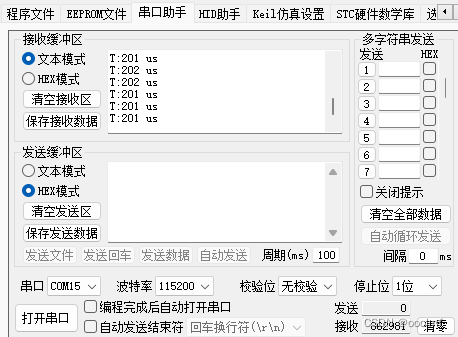
定时器1us定时一次