目录
前言
我们在参加许多轮式机器人比赛时,常常需要控制机器人的运动速度来控制机器人完成移动功能。绝倒多数的轮式机器人,如果想要做到比较精确的闭环控制,就需要用到一些特殊的控制算法,其中PID算法是众多控制算法中比较简单,且在工程界有着相当长的应用期。本文将介绍PID的基本原理、PID是如何在电机中应用的以及电机驱动相关内容。
PID算法简介
PID算法通常分为位置式PID和增量式PID,我们以位置式PID做简单介绍。
位置PID原理和公式
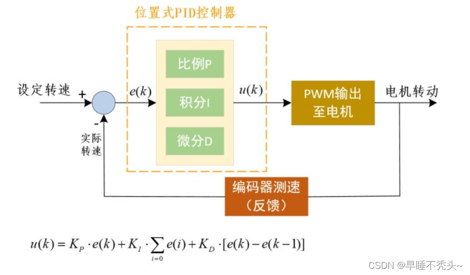
在控制小车运动时,常常会遇到给小车轮子设定固定转速,可是由于一些列的外界干扰导致轮子达不到设定的转速,以至于本应该走1m,小车实际只走了0.8m。这是我们可以利用位置式PID解决这个问题。

首先上图从左往右看,我们给轮子设定固定速度,例如1m/s,进入位置是PID控制器,内部执行u(k)公式,计算出的u(k)为电机转速PWM信号,然后通过编码器测出电机当前实际转速,用设定转速和实际转速相减得到了e(k),再次作用于PID控制器中进行运算,得出一个合适的PWM速度后作用于电机,再次通过编码器测速循环上午步骤,直e(k)为0。大体上通过PID控制器来计算出电机应该有多大的PWM转速来控制电机达到我们设定的转速。
那么如何通过编码器对电机测速呢?
如何用PID控制算法来控制电机保持或变化到固定速度(米每秒)呢?
首先我们介绍一个器件——正交编码器,很多大牛已经将正交编码器的原理讲的很好了,所以这里我们只说一下具体在工程中我们如何去使用。正交编码器可以测量电机轴转过一圈所产生的脉冲数,假如我们使用的编码器产生1440脉冲数表示电机转了一圈,那么这个参数除以轮子的周长,得到的数值单位是tick/m,其中tick表示脉冲,那么我们再将他乘以我们想要的速度(m/s),就可以得到一个单位是tick/s的量,他的物理含义是要达到我们设定的速度(m/s)我们每秒需要产生的脉冲数。我们加入设定程序执行周期是20ms,那么刚刚得到的数值乘以20ms,就可以知道想要达到我们设定的速度,在这20ms内需要产生多少个脉冲数。所以我们可以求出在这段时间内需要产生多少脉冲(设定值),然后和当前20ms产生多少脉冲(当前值)做差,就可以当作PID中的误差项,通过PID公式作用于电机的PWM占空比来控制电机转速,进而改变20ms内产生的脉冲数,最终当设定值和当前值相等时,PWM占空比将不再改变,电机维持在设置的固定转速。
说完思路,我们看看在stm32中具体如何实现
我们需要完成电机驱动、编码器驱动和PID控制算法的书写
电机部分驱动代码
电机驱动头文件:
void AX_MOTOR_Init(uint8_t freq_khz); //电机PWM控制初始化
void AX_MOTOR_A_SetSpeed(int16_t speed);   //电机A控制
void AX_MOTOR_B_SetSpeed(int16_t speed);   //电机B控制
void AX_MOTOR_C_SetSpeed(int16_t speed);   //电机C控制
void AX_MOTOR_D_SetSpeed(int16_t speed);   //电机D控制
主要有电机初始化函数和4个电机控制PWM函数,我们可以去设定定时器的预分频值和计数器的ARR来设定电机PWM频率,我们这里freq_khz范围是1-20,单位KHZ
在写电机驱动之前,先说说电机的硬件部分:

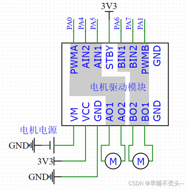
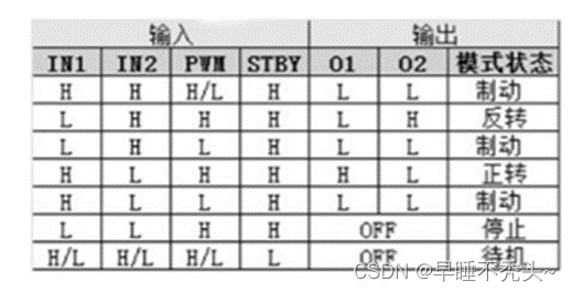
tb6612是一款常见的电机驱动芯片,单个芯片可以驱动两个电机,我们只关注左侧灰色框位置,例如我们使用的电机参数表如下图:

由于电机只有三种模式常用:正转、反转和制动,所以我们只需要关注这三个模式即可。
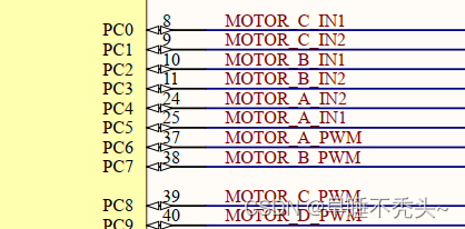
下面是tb6612于stm32的部分引脚连接图,我们以A电机为例,A电机符合上方逻辑图,当PC5和PC4引脚分别是高电平和低电平且PC6为高电平时电机正转,反转和制动同理。我们的项目中A,D电机符合上图逻辑图,但由于B,C电机的两个电机线反接,导致和上面逻辑图相反,即PC2和PC3为高电平和低电平时,电机反转,所以在电机控制代码的书写中也会相应做出调整。这个小细节会在后期PID控制中留下一个大坑,如果电机线反接会导致电机一上电就达到最大转速,这个问题后面会解释。

电机驱动.c文件:
/**
  * @简  述  电机PWM控制初始化
  * @参  数  freq_khz:PWM输出频率,范围1~20,单位KHz
  * @返回值  无
  */
void AX_MOTOR_Init(uint8_t freq_khz)
{

	GPIO_InitTypeDef GPIO_InitStructure;
	TIM_TimeBaseInitTypeDef  TIM_TimeBaseStructure;
	TIM_OCInitTypeDef  TIM_OCInitStructure;

	//定时器通道IO配置
	//GPIO及复用功能时钟使能
	RCC_APB2PeriphClockCmd(RCC_APB2Periph_GPIOC | RCC_APB2Periph_AFIO, ENABLE);

	//配置IO口为复用功能-定时器通道
	GPIO_InitStructure.GPIO_Pin =  GPIO_Pin_6 | GPIO_Pin_7 | GPIO_Pin_8 | GPIO_Pin_9;
	GPIO_InitStructure.GPIO_Mode = GPIO_Mode_AF_PP;
	GPIO_InitStructure.GPIO_Speed = GPIO_Speed_50MHz;
	GPIO_Init(GPIOC, &GPIO_InitStructure);

	//电机方向控制IO配置
	//IO时钟使能
	RCC_APB2PeriphClockCmd(RCC_APB2Periph_GPIOA | RCC_APB2Periph_GPIOC, ENABLE);

	//电机A方向控制IO
	GPIO_InitStructure.GPIO_Pin = GPIO_Pin_4 | GPIO_Pin_5;
	GPIO_InitStructure.GPIO_Mode = GPIO_Mode_Out_PP;
	GPIO_InitStructure.GPIO_Speed = GPIO_Speed_50MHz;
	GPIO_Init(GPIOC, &GPIO_InitStructure);

	//电机B方向控制IO
	GPIO_InitStructure.GPIO_Pin = GPIO_Pin_2 | GPIO_Pin_3;
	GPIO_Init(GPIOC, &GPIO_InitStructure);

	//电机C方向控制IO
	GPIO_InitStructure.GPIO_Pin = GPIO_Pin_0 | GPIO_Pin_1;
	GPIO_Init(GPIOC, &GPIO_InitStructure);

	//电机D方向控制IO
	GPIO_InitStructure.GPIO_Pin = GPIO_Pin_11 | GPIO_Pin_12;
	GPIO_Init(GPIOA, &GPIO_InitStructure);


	//定时器配置
	//参数过滤
	if(freq_khz == 0)
	freq_khz = 1;
	if(freq_khz > 20)
	freq_khz = 20;

	//TIM时钟使能
	RCC_APB2PeriphClockCmd(RCC_APB2Periph_TIM8, ENABLE);

	//Time base configuration
	TIM_TimeBaseStructure.TIM_Period = 2000-1;			//ARR
	TIM_TimeBaseStructure.TIM_Prescaler = 36/freq_khz-1;		//PSC
	TIM_TimeBaseStructure.TIM_ClockDivision = TIM_CKD_DIV1;//
	TIM_TimeBaseStructure.TIM_CounterMode = TIM_CounterMode_Up;
	TIM_TimeBaseInit(TIM8, &TIM_TimeBaseStructure);

	//PWM1 Mode configuration: Channel1
	TIM_OCInitStructure.TIM_OCMode = TIM_OCMode_PWM1;
	TIM_OCInitStructure.TIM_OutputState = TIM_OutputState_Enable;
	TIM_OCInitStructure.TIM_Pulse = 0;	    //占空比初始化		CRR
	TIM_OCInitStructure.TIM_OCPolarity = TIM_OCPolarity_High;
	TIM_OC1Init(TIM8, &TIM_OCInitStructure);
	TIM_OC1PreloadConfig(TIM8, TIM_OCPreload_Enable);

	//PWM1 Mode configuration: Channel2
	TIM_OC2Init(TIM8, &TIM_OCInitStructure);
	TIM_OC2PreloadConfig(TIM8, TIM_OCPreload_Enable);

	//PWM1 Mode configuration: Channel3
	TIM_OC3Init(TIM8, &TIM_OCInitStructure);
	TIM_OC3PreloadConfig(TIM8, TIM_OCPreload_Enable);

	//PWM1 Mode configuration: Channel4
	TIM_OC4Init(TIM8, &TIM_OCInitStructure);
	TIM_OC4PreloadConfig(TIM8, TIM_OCPreload_Enable);

	TIM_ARRPreloadConfig(TIM8, ENABLE);

	//TIM enable counter
	TIM_Cmd(TIM8, ENABLE);

	//使能MOE位	使用高级定时器时需要使能一下!
	TIM_CtrlPWMOutputs(TIM8,ENABLE);
}

/**
  * @简  述 电机A PWM速度控制
  * @参  数 speed 电机转速数值,范围-2000~2000
  * @返回值 无
  */
void AX_MOTOR_A_SetSpeed(int16_t speed)
{
	uint16_t temp;

  if(speed > 0)
	{
		GPIO_ResetBits(GPIOC, GPIO_Pin_4);
	  GPIO_SetBits(GPIOC, GPIO_Pin_5);
		temp = speed;
	}
	else if(speed < 0)
	{
		GPIO_ResetBits(GPIOC, GPIO_Pin_5);
	  GPIO_SetBits(GPIOC, GPIO_Pin_4);
		temp = (-speed);
	}
	else
	{
		GPIO_ResetBits(GPIOC, GPIO_Pin_4);
	  GPIO_ResetBits(GPIOC, GPIO_Pin_5);
		temp = 0;
	}

	if(temp>2000)
		temp = 2000;

	TIM_SetCompare1(TIM8,temp);
}

/**
  * @简  述 电机B PWM速度控制
  * @参  数 speed 电机转速数值,范围-2000~2000
  * @返回值 无
  */
void AX_MOTOR_B_SetSpeed(int16_t speed)
{
	uint16_t temp;

    if(speed > 0)
	{
		GPIO_ResetBits(GPIOC, GPIO_Pin_3);
	  GPIO_SetBits(GPIOC, GPIO_Pin_2);
		temp = speed;
	}
	else if(speed < 0)
	{
		GPIO_ResetBits(GPIOC, GPIO_Pin_2);
	  GPIO_SetBits(GPIOC, GPIO_Pin_3);
		temp = (-speed);
	}
	else
	{
		GPIO_ResetBits(GPIOC, GPIO_Pin_2);
	  GPIO_ResetBits(GPIOC, GPIO_Pin_3);
		temp = 0;
	}

	if(temp>2000)
		temp = 2000;

	TIM_SetCompare2(TIM8,temp);
}
/**
  * @简  述 电机C PWM速度控制
  * @参  数 speed 电机转速数值,范围-2000~2000
  * @返回值 无
  */
void AX_MOTOR_C_SetSpeed(int16_t speed)
{
	uint16_t temp;

  if(speed > 0)
	{
		GPIO_ResetBits(GPIOC, GPIO_Pin_0);
	  GPIO_SetBits(GPIOC, GPIO_Pin_1);
		temp = speed;
	}
	else if(speed < 0)
	{
		GPIO_ResetBits(GPIOC, GPIO_Pin_1);
	  GPIO_SetBits(GPIOC, GPIO_Pin_0);
		temp = (-speed);
	}
	else
	{
		GPIO_ResetBits(GPIOC, GPIO_Pin_1);
	  GPIO_ResetBits(GPIOC, GPIO_Pin_0);
		temp = 0;
	}

	if(temp>2000)
		temp = 2000;

	TIM_SetCompare3(TIM8,temp);
}

/**
  * @简  述 电机D PWM速度控制
  * @参  数 speed 电机转速数值,范围-2000~2000
  * @返回值 无
  */
void AX_MOTOR_D_SetSpeed(int16_t speed)
{
	uint16_t temp;

  if(speed > 0)
	{
		GPIO_ResetBits(GPIOA, GPIO_Pin_11);
	  GPIO_SetBits(GPIOA, GPIO_Pin_12);
		temp = speed;
	}
	else if(speed < 0)
	{
		GPIO_ResetBits(GPIOA, GPIO_Pin_12);
	  GPIO_SetBits(GPIOA, GPIO_Pin_11);
		temp = (-speed);
	}
	else
	{
		GPIO_ResetBits(GPIOA, GPIO_Pin_11);
	  GPIO_ResetBits(GPIOA, GPIO_Pin_12);
		temp = 0;
	}

	if(temp>2000)
		temp = 2000;

	TIM_SetCompare4(TIM8,temp);
}
上述为常见的电机驱动代码,故不做过多介绍。
编码器驱动部分代码
如何对编码器的脉冲计数呢?stm32正好在定时器中提供了编码器接口,专门用于对编码器脉冲进行计数。在stm32F103的板子中,T1和T8为高级定时器,T2、T3、T4、T5为通用定时器,通用定时器中有编码器接口,可以将T2-T5四个通用定时器中编码器接口和电机AB相相连,即Tx的通道1和通道2对应的是A相和B相。
下面是编码器驱动的头文件:
void AX_ENCODER_AB_Init(uint16_t cycle);          //编码器初始化
uint16_t AX_ENCODER_AB_GetCounter(void);          //编码器获取计数器数值
void AX_ENCODER_AB_SetCounter(uint16_t count);    //编码器设置计数器数值

void AX_ENCODER_CD_Init(uint16_t cycle);          //编码器初始化
uint16_t AX_ENCODER_CD_GetCounter(void);          //编码器获取计数器数值
void AX_ENCODER_CD_SetCounter(uint16_t count);    //编码器设置计数器数值

void AX_ENCODER_EF_Init(uint16_t cycle);          //编码器初始化
uint16_t AX_ENCODER_EF_GetCounter(void);          //编码器获取计数器数值
void AX_ENCODER_EF_SetCounter(uint16_t count);    //编码器设置计数器数值

void AX_ENCODER_GH_Init(uint16_t cycle);          //编码器初始化
uint16_t AX_ENCODER_GH_GetCounter(void);          //编码器获取计数器数值
void AX_ENCODER_GH_SetCounter(uint16_t count);    //编码器设置计数器数值
编码器源文件(先别急,后面会做简单解读):
/**
  * @简  述  编码器AB初始化
  * @参  数  cycle:计数周期
  * @返回值  无
  */
void AX_ENCODER_AB_Init(uint16_t cycle)
{
	GPIO_InitTypeDef GPIO_InitStructure;
	TIM_TimeBaseInitTypeDef  TIM_TimeBaseStructure;
	TIM_ICInitTypeDef TIM_ICInitStructure;

	//GPIO功能时钟使能
	RCC_APB2PeriphClockCmd(RCC_APB2Periph_GPIOA | RCC_APB2Periph_GPIOB | RCC_APB2Periph_AFIO, ENABLE);

	GPIO_PinRemapConfig(GPIO_FullRemap_TIM2, ENABLE);

	//配置IO口为复用功能-定时器通道
	GPIO_InitStructure.GPIO_Pin =  GPIO_Pin_3;
	GPIO_InitStructure.GPIO_Mode = GPIO_Mode_IN_FLOATING;        //复用功能
	GPIO_InitStructure.GPIO_Speed = GPIO_Speed_50MHz;	//速度100MHz
	GPIO_Init(GPIOB, &GPIO_InitStructure);

	GPIO_InitStructure.GPIO_Pin =  GPIO_Pin_15;
	GPIO_Init(GPIOA, &GPIO_InitStructure);

	//TIM时钟使能
	RCC_APB1PeriphClockCmd(RCC_APB1Periph_TIM2, ENABLE);

	//Timer configuration in Encoder mode
	TIM_DeInit(TIM2);
	TIM_TimeBaseStructInit(&TIM_TimeBaseStructure);

	TIM_TimeBaseStructure.TIM_Prescaler = 0x0;  // No prescaling
	TIM_TimeBaseStructure.TIM_Period = cycle;
	TIM_TimeBaseStructure.TIM_ClockDivision = TIM_CKD_DIV1;
	TIM_TimeBaseStructure.TIM_CounterMode = TIM_CounterMode_Up;
	TIM_TimeBaseInit(TIM2, &TIM_TimeBaseStructure);

	TIM_EncoderInterfaceConfig(TIM2, TIM_EncoderMode_TI12, TIM_ICPolarity_Rising, TIM_ICPolarity_Rising);
	TIM_ICStructInit(&TIM_ICInitStructure);
	TIM_ICInitStructure.TIM_ICFilter = 6;
	TIM_ICInit(TIM2, &TIM_ICInitStructure);

	//Reset counter
	TIM2->CNT = 0;

	TIM_Cmd(TIM2, ENABLE);
}

/**
  * @简  述  编码器AB获取计数器数值
  * @参  数  无
  * @返回值  计数器当前值
  */
uint16_t AX_ENCODER_AB_GetCounter(void)
{
	return (TIM_GetCounter(TIM2));
}

/**
  * @简  述  编码器AB设置计数器数值
  * @参  数  count  计数器数值
  * @返回值  无
  */
void AX_ENCODER_AB_SetCounter(uint16_t count)
{
	TIM2->CNT = count;
}

/**
  * @简  述  编码器CD初始化
  * @参  数  cycle:计数周期
  * @返回值  无
  */
void AX_ENCODER_CD_Init(uint16_t cycle)
{
	GPIO_InitTypeDef GPIO_InitStructure;
	TIM_TimeBaseInitTypeDef  TIM_TimeBaseStructure;
	TIM_ICInitTypeDef TIM_ICInitStructure;

	//GPIO功能时钟使能
	RCC_APB2PeriphClockCmd(RCC_APB2Periph_GPIOB | RCC_APB2Periph_AFIO, ENABLE);

	//配置IO口为复用功能-定时器通道
	GPIO_InitStructure.GPIO_Pin =  GPIO_Pin_4 | GPIO_Pin_5;
	GPIO_InitStructure.GPIO_Mode = GPIO_Mode_IN_FLOATING;        //复用功能
	GPIO_InitStructure.GPIO_Speed = GPIO_Speed_50MHz;	//速度100MHz
	GPIO_Init(GPIOB, &GPIO_InitStructure);

	//TIM时钟使能
	RCC_APB1PeriphClockCmd(RCC_APB1Periph_TIM3, ENABLE);

	GPIO_PinRemapConfig(GPIO_PartialRemap_TIM3 , ENABLE); //这个就是重映射功能函数

	//Timer configuration in Encoder mode
	TIM_DeInit(TIM3);
	TIM_TimeBaseStructInit(&TIM_TimeBaseStructure);

	TIM_TimeBaseStructure.TIM_Prescaler = 0x0;  // No prescaling
	TIM_TimeBaseStructure.TIM_Period = cycle;
	TIM_TimeBaseStructure.TIM_ClockDivision = TIM_CKD_DIV1;
	TIM_TimeBaseStructure.TIM_CounterMode = TIM_CounterMode_Up;
	TIM_TimeBaseInit(TIM3, &TIM_TimeBaseStructure);

	TIM_EncoderInterfaceConfig(TIM3, TIM_EncoderMode_TI12, TIM_ICPolarity_Rising, TIM_ICPolarity_Rising);
	TIM_ICStructInit(&TIM_ICInitStructure);
	TIM_ICInitStructure.TIM_ICFilter = 6;
	TIM_ICInit(TIM3, &TIM_ICInitStructure);

	//Reset counter
	TIM3->CNT = 0;

	TIM_Cmd(TIM3, ENABLE);
}

/**
  * @简  述  编码器CD获取计数器数值
  * @参  数  无
  * @返回值  计数器当前值
  */
uint16_t AX_ENCODER_CD_GetCounter(void)
{
	return (TIM_GetCounter(TIM3));
}

/**
  * @简  述  编码器CD设置计数器数值
  * @参  数  count  计数器数值
  * @返回值  无
  */
void AX_ENCODER_CD_SetCounter(uint16_t count)
{
	TIM3->CNT = count;
}

/**
  * @简  述  编码器EF初始化
  * @参  数  cycle:计数周期
  * @返回值  无
  */
void AX_ENCODER_EF_Init(uint16_t cycle)
{
	GPIO_InitTypeDef GPIO_InitStructure;
	TIM_TimeBaseInitTypeDef  TIM_TimeBaseStructure;
	TIM_ICInitTypeDef TIM_ICInitStructure;

	//GPIO功能时钟使能
	RCC_APB2PeriphClockCmd(RCC_APB2Periph_GPIOB, ENABLE);

	//配置IO口为复用功能-定时器通道
	GPIO_InitStructure.GPIO_Pin =  GPIO_Pin_6 | GPIO_Pin_7;
	GPIO_InitStructure.GPIO_Mode = GPIO_Mode_IN_FLOATING;        //复用功能
	GPIO_InitStructure.GPIO_Speed = GPIO_Speed_50MHz;	//速度100MHz
	GPIO_Init(GPIOB, &GPIO_InitStructure);

	//TIM时钟使能
	RCC_APB1PeriphClockCmd(RCC_APB1Periph_TIM4, ENABLE);

	//Timer configuration in Encoder mode
	TIM_DeInit(TIM4);
	TIM_TimeBaseStructInit(&TIM_TimeBaseStructure);

	TIM_TimeBaseStructure.TIM_Prescaler = 0x0;  // No prescaling
	TIM_TimeBaseStructure.TIM_Period = cycle;
	TIM_TimeBaseStructure.TIM_ClockDivision = TIM_CKD_DIV1;
	TIM_TimeBaseStructure.TIM_CounterMode = TIM_CounterMode_Up;
	TIM_TimeBaseInit(TIM4, &TIM_TimeBaseStructure);

	TIM_EncoderInterfaceConfig(TIM4, TIM_EncoderMode_TI12, TIM_ICPolarity_Rising, TIM_ICPolarity_Rising);
	TIM_ICStructInit(&TIM_ICInitStructure);
	TIM_ICInitStructure.TIM_ICFilter = 6;
	TIM_ICInit(TIM4, &TIM_ICInitStructure);

	//Reset counter
	TIM4->CNT = 0;

	TIM_Cmd(TIM4, ENABLE);
}

/**
  * @简  述  编码器EF获取计数器数值
  * @参  数  无
  * @返回值  计数器当前值
  */
uint16_t AX_ENCODER_EF_GetCounter(void)
{
	return (TIM_GetCounter(TIM4));
}

/**
  * @简  述  编码器EF设置计数器数值
  * @参  数  count  计数器数值
  * @返回值  无
  */
void AX_ENCODER_EF_SetCounter(uint16_t count)
{
	TIM4->CNT = count;
}

/**
  * @简  述  编码器GH初始化
  * @参  数  cycle:计数周期
  * @返回值  无
  */
void AX_ENCODER_GH_Init(uint16_t cycle)
{
	GPIO_InitTypeDef GPIO_InitStructure;
	TIM_TimeBaseInitTypeDef  TIM_TimeBaseStructure;
	TIM_ICInitTypeDef TIM_ICInitStructure;

	//GPIO功能时钟使能
	RCC_APB2PeriphClockCmd(RCC_APB2Periph_GPIOA, ENABLE);

	//配置IO口为复用功能-定时器通道
	GPIO_InitStructure.GPIO_Pin =  GPIO_Pin_0 | GPIO_Pin_1;
	GPIO_InitStructure.GPIO_Mode = GPIO_Mode_IN_FLOATING;        //复用功能
	GPIO_InitStructure.GPIO_Speed = GPIO_Speed_50MHz;	//速度100MHz
	GPIO_Init(GPIOA, &GPIO_InitStructure);

	//TIM时钟使能
	RCC_APB1PeriphClockCmd(RCC_APB1Periph_TIM5, ENABLE);

	//Timer configuration in Encoder mode
	TIM_DeInit(TIM5);
	TIM_TimeBaseStructInit(&TIM_TimeBaseStructure);

	TIM_TimeBaseStructure.TIM_Prescaler = 0x0;  // No prescaling
	TIM_TimeBaseStructure.TIM_Period = cycle;
	TIM_TimeBaseStructure.TIM_ClockDivision = TIM_CKD_DIV1;
	TIM_TimeBaseStructure.TIM_CounterMode = TIM_CounterMode_Up;
	TIM_TimeBaseInit(TIM5, &TIM_TimeBaseStructure);

	TIM_EncoderInterfaceConfig(TIM5, TIM_EncoderMode_TI12, TIM_ICPolarity_Rising, TIM_ICPolarity_Rising);
	TIM_ICStructInit(&TIM_ICInitStructure);
	TIM_ICInitStructure.TIM_ICFilter = 6;
	TIM_ICInit(TIM5, &TIM_ICInitStructure);

	//Reset counter
	TIM5->CNT = 0;

	TIM_Cmd(TIM5, ENABLE);
}

/**
  * @简  述  编码器GH获取计数器数值
  * @参  数  无
  * @返回值  计数器当前值
  */
uint16_t AX_ENCODER_GH_GetCounter(void)
{
	return (TIM_GetCounter(TIM5));
}

/**
  * @简  述  编码器GH设置计数器数值
  * @参  数  count  计数器数值
  * @返回值  无
  */
void AX_ENCODER_GH_SetCounter(uint16_t count)
{
	TIM5->CNT = count;
}
定时器初始化时传入的参数cycle是定时器的最大计数值也就是CRR,我们将cycle设置为60000,由于最一开始我们说选用的编码器产生1440个脉冲表示电机转一圈,所以我们获取定时器计数值等于1440零时,就可以知道电机转过了一圈,再除以时间我们就得到了转速。
通常我们先设定计数器的值为30000(1半的量程)。要知道在这20ms中编码器产生了多少脉冲,有很多方法,我们介绍一种较为简单的,在程序执行开始时获取当前编码器的脉冲数,然后和定时器初始值30000相减,得到在这20ms内编码器所产生的脉冲数,然后将计数器数值设置为初始数值30000(这里设置为初始值是为了下一次相减做准备,过了20ms后他将增加一些脉冲数,和下一个20ms内的30000相减就可以得到下一个周期编码器脉冲变化值),这样我们就可以准确测出电机在20ms内转动产生了多少编码器脉冲。我们只需要将这个实际产生的脉冲值和我们上面所得到的期望脉冲值(期望的速度对应的20ms内编码器产生的脉冲值)做差,得到的就是我们PID中的error,通过PID对error进行运算来改变电机的转速,逐渐使得error变小直到为0(关于PID方面的基础知识省略)。
但是还有一个问题,就是我们电机正反转,如果搞错了电机正反转,那么PID中的负反馈将会变成正反馈,假如电机通过PID运算后应该正向旋转来减小误差值,可是电机线接反或者引脚定义出错导致电机进行了反转,再次经过PID运算后得到了更强烈的正转,但是电机实际进行了更强烈的反转,由于我们PID控制周期设置的是20ms,所以电机一上电很快就达到了最快转速,这就是我们说的负反馈变成了正反馈。下面我们以最常见的TB6612电机驱动芯片进行电机正反转的介绍:
PID控制算法部分
我们选取PID控制频率是50HZ
/**
  * @简  述  电机A PID控制函数
  * @参  数  spd_target:编码器速度目标值 ,范围(±250)
  *          spd_current: 编码器速度当前值
  * @返回值  电机PWM速度
  */
int16_t AX_PID_MotorVelocityCtlA(int16_t spd_target, int16_t spd_current)
{
	static int16_t motor_pwm_out;
	static int32_t bias,bias_last,bias_integral = 0;

	//获得偏差值
	bias = spd_target - spd_current;

	//计算偏差累加值
	bias_integral += bias;

	//抗积分饱和
	if(bias_integral>PID_INTEGRAL_UP)bias_integral = PID_INTEGRAL_UP;
	if(bias_integral<-PID_INTEGRAL_UP)bias_integral = -PID_INTEGRAL_UP;

	//PID计算电机输出PWM值
	motor_pwm_out += ax_motor_kp*bias*PID_SCALE + ax_motor_kd*(bias-bias_last)*PID_SCALE + ax_motor_ki*bias_integral*PID_SCALE;

	//记录上次偏差
	bias_last = bias;

	//限制最大输出
	if(motor_pwm_out > 2000)
		motor_pwm_out = 2000;
	if(motor_pwm_out < -2000)
		motor_pwm_out = -2000;

	//返回PWM控制值
	return motor_pwm_out;
}