目录
一、资料下载
最近要用SX1281做一款产品,把学习过程记录下,以便后期查阅。
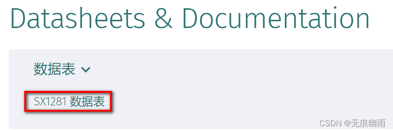
1、中文手册下载地址:
DS_SX1280-1-2_V3.0_SC.zip_sx1280中文手册-其它文档类资源-CSDN下载
2、英文手册下载地址:
SX1281 | 长距离低功耗 2.4 GHz 射频收发器 | Semtech
?3、固件下载地址:
SX1281 | 长距离低功耗 2.4 GHz 射频收发器 | Semtech

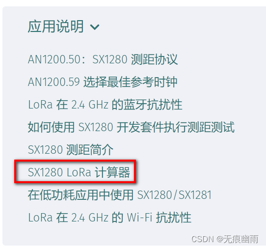
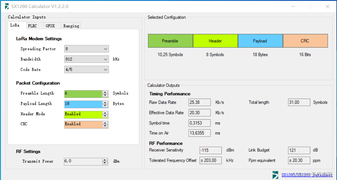
4、SX1281的速率计算器下载地址:
SX1280 | 长距离低功耗 2.4 GHz 射频收发器 | Semtech
5、SX128X区别:
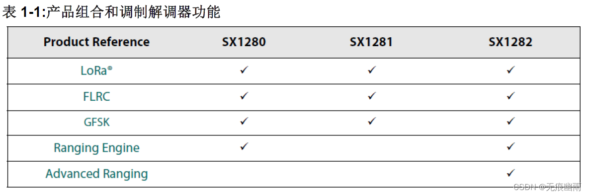
?SX1281不支持测距功能;SX1280支持普通测试功能,不支持高级测距功能;SX1282支持普通测距和高级测距功能。如果仅仅用作数据传输,三款芯片没有区别。
二、驱动讲解
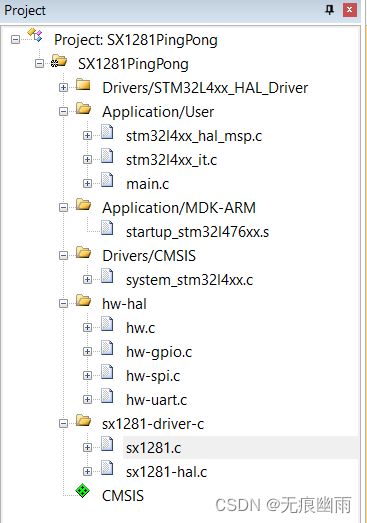
下载SX1281DemoCodeDriver-C.zip固件包,解压缩后,打开工程,环境如下:
1)软件:MDK V5;
2)MCU型号:STM32L476RGTx;
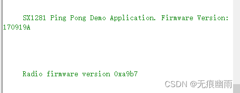
3)固件版本为:Firmware Version: 170919A;
工程如下图所示:
?和SX1281相关文件如下图所示,一共5个文件:
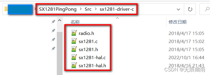
1、radio.h文件?
其中radio.h为接口抽象文件,把和SX128X相关操作,全部抽象为API接口,官方提供,无需更改。
struct Radio_s
{
    /*!
     * \brief Initializes the radio
     *
     * \param [IN] callbacks Structure containing the driver callback functions
     */
    void ( *Init )( RadioCallbacks_t *callbacks );

    /*!
     * \brief Resets the radio
     */
    void ( *Reset )( void );

    /*!
     * \brief Gets the current radio status
     *
     * \retval      status        Radio status
     */
    RadioStatus_t ( *GetStatus )( void );

    /*!
     * \brief Writes the given command to the radio
     *
     * \param [in]  opcode        Command opcode
     * \param [in]  buffer        Command parameters byte array
     * \param [in]  size          Command parameters byte array size
     */
    void ( *WriteCommand )( RadioCommands_t opcode, uint8_t *buffer, uint16_t size );

    /*!
     * \brief Reads the given command from the radio
     *
     * \param [in]  opcode        Command opcode
     * \param [in]  buffer        Command parameters byte array
     * \param [in]  size          Command parameters byte array size
     */
    void ( *ReadCommand )( RadioCommands_t opcode, uint8_t *buffer, uint16_t size );

    /*!
     * \brief Writes multiple radio registers starting at address
     *
     * \param [in]  address       First Radio register address
     * \param [in]  buffer        Buffer containing the new register's values
     * \param [in]  size          Number of registers to be written
     */
    void ( *WriteRegisters )( uint16_t address, uint8_t *buffer, uint16_t size );

    /*!
     * \brief Writes the radio register at the specified address
     *
     * \param [in]  address       Register address
     * \param [in]  value         New register value
     */
    void ( *WriteRegister )( uint16_t address, uint8_t value );

    /*!
     * \brief Reads multiple radio registers starting at address
     *
     * \param [in]  address       First Radio register address
     * \param [out] buffer        Buffer where to copy the registers data
     * \param [in]  size          Number of registers to be read
     */
    void ( *ReadRegisters )( uint16_t address, uint8_t *buffer, uint16_t size );

    /*!
     * \brief Reads the radio register at the specified address
     *
     * \param [in]  address       Register address
     *
     * \retval      value         The register value
     */
    uint8_t ( *ReadRegister )( uint16_t address );

    /*!
     * \brief Writes Radio Data Buffer with buffer of size starting at offset.
     *
     * \param [in]  offset        Offset where to start writing
     * \param [in]  buffer        Buffer pointer
     * \param [in]  size          Buffer size
     */
    void ( *WriteBuffer )( uint8_t offset, uint8_t *buffer, uint8_t size );

    /*!
     * \brief Reads Radio Data Buffer at offset to buffer of size
     *
     * \param [in]  offset        Offset where to start reading
     * \param [out] buffer        Buffer pointer
     * \param [in]  size          Buffer size
     */
    void ( *ReadBuffer )( uint8_t offset, uint8_t *buffer, uint8_t size );

    /*!
     * \brief Gets the current status of the radio DIOs
     *
     * \retval      status        [Bit #3: DIO3, Bit #2: DIO2,
     *                             Bit #1: DIO1, Bit #0: BUSY]
     */
    uint8_t ( *GetDioStatus )( void );

    /*!
     * \brief Return firmware version
     *
     * \retval      firmware      The firmware version
     */
    uint16_t ( *GetFirmwareVersion )( void );

    /*!
     * \brief Sets the power regulators operating mode
     *
     * \param [in]  mode          [0: LDO, 1:DC_DC]
     */
    void ( *SetRegulatorMode )( RadioRegulatorModes_t mode );

    /*!
     * \brief Sets the radio in configuration mode
     *
     * \param [in]  mode          The standby mode to put the radio into
     */
    void ( *SetStandby )( RadioStandbyModes_t mode );

    /*!
     * \brief Sets the radio for the given protocol
     *
     * \param [in]  packetType    [PACKET_TYPE_GFSK, PACKET_TYPE_LORA,
     *                             PACKET_TYPE_FLRC, PACKET_TYPE_BLE]
     *
     * \remark This method has to be called before SetRfFrequency,
     *         SetModulationParams and SetPacketParams
     */
    void ( *SetPacketType )( RadioPacketTypes_t packetType );

    /*!
     * \brief Set the modulation parameters
     *
     * \param [in]  modParams     A structure describing the modulation parameters
     */
    void ( *SetModulationParams )( ModulationParams_t *modParams );

    /*!
     * \brief Sets the packet parameters
     *
     * \param [in]  packetParams  A structure describing the packet parameters
     */
    void ( *SetPacketParams )( PacketParams_t *packetParams );

    /*!
     * \brief Sets the RF frequency
     *
     * \param [in]  frequency     RF frequency [Hz]
     */
    void ( *SetRfFrequency )( uint32_t frequency );

    /*!
     * \brief Sets the data buffer base address for transmission and reception
     *
     * \param [in]  txBaseAddress Transmission base address
     * \param [in]  rxBaseAddress Reception base address
     */
    void ( *SetBufferBaseAddresses )( uint8_t txBaseAddress, uint8_t rxBaseAddress );

    /*!
     * \brief Sets the transmission parameters
     *
     * \param [in]  power         RF output power [-18..13] dBm
     * \param [in]  rampTime      Transmission ramp up time
     */
    void ( *SetTxParams )( int8_t power, RadioRampTimes_t rampTime );

    /*!
     * \brief   Sets the IRQ mask and DIO masks
     *
     * \param [in]  irqMask       General IRQ mask
     * \param [in]  dio1Mask      DIO1 mask
     * \param [in]  dio2Mask      DIO2 mask
     * \param [in]  dio3Mask      DIO3 mask
     */
    void ( *SetDioIrqParams )( uint16_t irqMask, uint16_t dio1Mask, uint16_t dio2Mask, uint16_t dio3Mask );

    /*!
     * \brief Sets the Sync Word given by index used in GFSK, FLRC and BLE protocols
     *
     * \remark 5th byte isn't used in FLRC and BLE protocols
     *
     * \param [in]  syncWordIdx   Index of SyncWord to be set [1..3]
     * \param [in]  syncWord      SyncWord bytes ( 5 bytes )
     *
     * \retval      status        [0: OK, 1: NOK]
     */
    uint8_t ( *SetSyncWord )( uint8_t syncWordIdx, uint8_t *syncWord );

    /*!
     * \brief Sets the radio in reception mode
     *
     * \param [in]  timeout       Structure describing the reception timeout value
     */
    void ( *SetRx )( TickTime_t timeout );

    /*!
     * \brief Reads the payload received. If the received payload is longer
     * than maxSize, then the method returns 1 and do not set size and payload.
     *
     * \param [out] payload       A pointer to a buffer into which the payload will be copied
     * \param [out] size          A pointer to the size of the payload received
     * \param [in]  maxSize       The maximal size allowed to copy into the buffer
     */
    uint8_t ( *GetPayload )( uint8_t *payload, uint8_t *size, uint8_t maxSize );

    /*!
     * \brief Sends a payload
     *
     * \param [in]  payload       A pointer to the payload to send
     * \param [in]  size          The size of the payload to send
     * \param [in]  timeout       The timeout for Tx operation
     */
    void ( *SendPayload )( uint8_t *payload, uint8_t size, TickTime_t timeout );

    /*!
     * \brief Set the driver in polling mode.
     *
     * In polling mode the application is responsible to call ProcessIrqs( ) to
     * execute callbacks functions.
     * The default mode is Interrupt Mode.
     * @code
     * // Initializations and callbacks declaration/definition
     * radio = SX1281( mosi, miso, sclk, nss, busy, int1, int2, int3, rst, &callbacks );
     * radio.Init( );
     * radio.SetPollingMode( );
     *
     * while( true )
     * {
     *                            //     IRQ processing is automatically done
     *     radio.ProcessIrqs( );  // <-- here, as well as callback functions
     *                            //     calls
     *     // Do some applicative work
     * }
     * @endcode
     *
     * \see SX1281SetInterruptMode
     */
    void ( *SetPollingMode )( void );

    /*!
     * \brief Set the driver in interrupt mode.
     *
     * In interrupt mode, the driver communicate with the radio during the
     * interruption by direct calls to ProcessIrqs( ). The main advantage is
     * the possibility to have low power application architecture.
     * This is the default mode.
     * @code
     * // Initializations and callbacks declaration/definition
     * radio = SX1281( mosi, miso, sclk, nss, busy, int1, int2, int3, rst, &callbacks );
     * radio.Init( );
     * radio.SetInterruptMode( );   // Optionnal. Driver default behavior
     *
     * while( true )
     * {
     *     // Do some applicative work
     * }
     * @endcode
     *
     * \see SX1281SetPollingMode
     */
    void ( *SetInterruptMode )( void );

    /*!
     * \brief Initializes the radio registers to the recommended default values
     */
    void ( *SetRegistersDefault )( void );

    /*!
     * \brief Gets the current Operation Mode of the Radio
     *
     * \retval      RadioOperatingModes_t last operating mode
     */
    RadioOperatingModes_t ( *GetOpMode )( void );

    /*!
     * \brief Sets the radio in sleep mode
     *
     * \param [in]  sleepConfig   The sleep configuration describing data
     *                            retention and RTC wake-up
     */
    void ( *SetSleep )( SleepParams_t sleepConfig );

    /*!
     * \brief Sets the radio in FS mode
     */
    void ( *SetFs )( void );

    /*!
     * \brief Sets the radio in transmission mode
     *
     * \param [in]  timeout       Structure describing the transmission timeout value
     */
    void ( *SetTx )( TickTime_t timeout );

    /*!
     * \brief Sets the Rx duty cycle management parameters
     *
     * \param [in]  rxTime        Structure describing reception timeout value
     * \param [in]  sleepTime     Structure describing sleep timeout value
     */
    void ( *SetRxDutyCycle )( RadioTickSizes_t Step, uint16_t NbStepRx, uint16_t RxNbStepSleep );

    /*!
     * \brief Sets the radio in CAD mode
     *
     * \see SX1281::SetCadParams
     */
    void ( *SetCad )( void );

    /*!
     * \brief Sets the radio in continuous wave transmission mode
     */
    void ( *SetTxContinuousWave )( void );

    /*!
     * \brief Sets the radio in continuous preamble transmission mode
     */
    void ( *SetTxContinuousPreamble )( void );

    /*!
     * \brief Gets the current radio protocol
     *
     * \retval      packetType    [PACKET_TYPE_GFSK, PACKET_TYPE_LORA,
     *                             PACKET_TYPE_FLRC, PACKET_TYPE_BLE, PACKET_TYPE_NONE]
     */
    RadioPacketTypes_t ( *GetPacketType )( void );

    /*!
     * \brief Sets the number of symbols to be used for Channel Activity
     *        Detection operation
     *
     * \param [in]  cadSymbolNum  The number of symbol to use for Channel Activity
     *                            Detection operations [LORA_CAD_01_SYMBOL, LORA_CAD_02_SYMBOL,
     *                            LORA_CAD_04_SYMBOL, LORA_CAD_08_SYMBOL, LORA_CAD_16_SYMBOL]
     */
    void ( *SetCadParams )( RadioLoRaCadSymbols_t cadSymbolNum );

    /*!
     * \brief Gets the last received packet buffer status
     *
     * \param [out] payloadLength Last received packet payload length
     * \param [out] rxStartBuffer Last received packet buffer address pointer
     */
    void ( *GetRxBufferStatus )( uint8_t *payloadLength, uint8_t *rxStartBuffer );

    /*!
     * \brief Gets the last received packet payload length
     *
     * \param [out] pktStatus     A structure of packet status
     */
    void ( *GetPacketStatus )( PacketStatus_t *pktStatus );

    /*!
     * \brief Returns the instantaneous RSSI value for the last packet received
     *
     * \retval      rssiInst      Instantaneous RSSI
     */
    int8_t ( *GetRssiInst )( void );

    /*!
     * \brief Returns the current IRQ status
     *
     * \retval      irqStatus     IRQ status
     */
    uint16_t ( *GetIrqStatus )( void );

    /*!
     * \brief Clears the IRQs
     *
     * \param [in]  irq           IRQ(s) to be cleared
     */
    void ( *ClearIrqStatus )( uint16_t irq );

    /*!
     * \brief Calibrates the given radio block
     *
     * \param [in]  calibParam    The description of blocks to be calibrated
     */
    void ( *Calibrate )( CalibrationParams_t calibParam );

    /*!
     * \brief Saves the current selected modem configuration into data RAM
     */
    void ( *SetSaveContext )( void );

    /*!
     * \brief Sets the chip to automatically send a packet after the end of a packet reception
     *
     * \remark The offset is automatically compensated inside the function
     *
     * \param [in]  time          The delay in us after which a Tx is done
     */
    void ( *SetAutoTx )( uint16_t time );

    /*!
     * \brief Sets the chip to automatically receive a packet after the end of a packet transmission
     *
     * \remark The offset is automatically compensated inside the function
     *
     * \param [in]  time          The delay in us after which a Rx is done
     */
    void ( *SetAutoFS )( uint8_t enable );

    /*!
     * \brief Enables or disables long preamble detection mode
     *
     * \param [in]  enable        [0: Disable, 1: Enable]
     */
    void ( *SetLongPreamble )( uint8_t enable );

    /*!
     * \brief Saves the payload to be send in the radio buffer
     *
     * \param [in]  payload       A pointer to the payload
     * \param [in]  size          The size of the payload
     */
    void ( *SetPayload )( uint8_t *payload, uint8_t size );

    /*!
     * \brief Sets the Sync Word given by index used in GFSK, FLRC and BLE protocols
     *
     * \remark 5th byte isn't used in FLRC and BLE protocols
     *
     * \param [in]  syncWordIdx   Index of SyncWord to be set [1..3]
     * \param [in]  syncWord      SyncWord bytes ( 5 bytes )
     *
     * \retval      status        [0: OK, 1: NOK]
     */
    void ( *SetSyncWordErrorTolerance )( uint8_t errorBits );

    /*!
     * \brief Sets the Initial value for the LFSR used for the CRC calculation
     *
     * \param [in]  seed          Initial LFSR value ( 4 bytes )
     *
     */
    void ( *SetCrcSeed )( uint16_t seed );

    /*!
     * \brief Set the Access Address field of BLE packet
     *
     * \param [in]  accessAddress The access address to be used for next BLE packet sent
     *
     * \see SX1281::SetBleAdvertizerAccessAddress
     */
    void ( *SetBleAccessAddress )( uint32_t accessAddress );

    /*!
     * \brief Set the Access Address for Advertizer BLE packets
     *
     * All advertizer BLE packets must use a particular value for Access
     * Address field. This method sets it.
     *
     * \see SX1281::SetBleAccessAddress
     */
    void ( *SetBleAdvertizerAccessAddress )( void );


    /*!
     * \brief Sets the seed used for the CRC calculation
     *
     * \param [in]  seed          The seed value
     *
     */
    void ( *SetCrcPolynomial )( uint16_t seed );

    /*!
     * \brief Sets the Initial value of the LFSR used for the whitening in GFSK, FLRC and BLE protocols
     *
     * \param [in]  seed          Initial LFSR value
     */
    void ( *SetWhiteningSeed )( uint8_t seed );

    /*!
     * \brief Return the Estimated Frequency Error in LORA operations
     *
     * \retval efe                The estimated frequency error [Hz]
     */
    double ( *GetFrequencyError )( void );
};
2、sx1281.c文件
?sx1281.c为实现文件,实现上述所有接口,官方提供,无需更改。
3、sx1281-hal.c文件
sx1281-hal.c为SX1281驱动和用户之间提供实现层:
1)Radio变量提供radio.h抽象的实例,便于用于通过它调用sx1281.c的函数。
2)需要用户提供:HAL_Delay()、GpioWrite()、GpioRead、SpiInOut()、SpiIn()等函数。
3)HAL_Delay()函数实现:这个函数就是一个延时函数,根据手册自己设定,为了调试,这里实现了一个ms级的软件延时函数。
4)GpioWrite()函数实现:
HAL库:
void GpioWrite( GPIO_TypeDef* GPIOx, uint16_t GPIO_Pin, uint32_t value )
{
    HAL_GPIO_WritePin( GPIOx, GPIO_Pin , ( GPIO_PinState ) value );
}
LL库:
#define GpioWrite(__PORT,__PIN,VALUE)   do{                                          \
                                            if(VALUE){                               \
                                                LL_GPIO_SetOutputPin(__PORT,__PIN);  \
                                            }else{                                   \
                                                LL_GPIO_ResetOutputPin(__PORT,__PIN);\
                                            }                                        \
                                        }while(0);
4)GpioRead()函数实现:
HAL库:
uint32_t GpioRead( GPIO_TypeDef* GPIOx, uint16_t GPIO_Pin )
{
    return HAL_GPIO_ReadPin( GPIOx, GPIO_Pin );
}
LL库:
#define GPIO_READ_BIT(__GPIO,__PIN)     LL_GPIO_IsInputPinSet(__GPIO,__PIN)

#define GpioRead(__GPIO,__PIN)          GPIO_READ_BIT(__GPIO,__PIN)
5)SpiInOut()函数实现:
HAL库:
/*!
 * @brief Sends txBuffer and receives rxBuffer
 *
 * @param [IN] txBuffer Byte to be sent
 * @param [OUT] rxBuffer Byte to be sent
 * @param [IN] size Byte to be sent
 */
void SpiInOut( uint8_t *txBuffer, uint8_t *rxBuffer, uint16_t size )
{
    HAL_SPIEx_FlushRxFifo( &SpiHandle );
    #ifdef USE_DMA
        blockingDmaFlag = true;
        HAL_SPI_TransmitReceive_DMA( &SpiHandle, txBuffer, rxBuffer, size );
        WAIT_FOR_BLOCKING_FLAG
    #else
        HAL_SPI_TransmitReceive( &SpiHandle, txBuffer, rxBuffer, size, HAL_MAX_DELAY );
    #endif
}
这里有传入了一个发送数组首地址、一个接收数组首地址,还有一个长度;我的疑问是先把数据发送出去,再接收,还是发送一个字节,接收一个字节。往下看底层函数HAL_SPI_TransmitReceive(因为HAL_SPI_TransmitReceive_DMA和HAL_SPI_TransmitReceive实现功能是一样的):
    while ((hspi->TxXferCount > 0U) || (hspi->RxXferCount > 0U))
    {
      /* check TXE flag */
      if (txallowed && (hspi->TxXferCount > 0U) && (__HAL_SPI_GET_FLAG(hspi, SPI_FLAG_TXE)))
      {
        if (hspi->TxXferCount > 1U)
        {
          hspi->Instance->DR = *((uint16_t *)pTxData);
          pTxData += sizeof(uint16_t);
          hspi->TxXferCount -= 2U;
        }
        else
        {
          *(__IO uint8_t *)&hspi->Instance->DR = (*pTxData++);
          hspi->TxXferCount--;
        }
        /* Next Data is a reception (Rx). Tx not allowed */
        txallowed = 0U;

#if (USE_SPI_CRC != 0U)
        /* Enable CRC Transmission */
        if ((hspi->TxXferCount == 0U) && (hspi->Init.CRCCalculation == SPI_CRCCALCULATION_ENABLE))
        {
          /* Set NSS Soft to received correctly the CRC on slave mode with NSS pulse activated */
          if (((hspi->Instance->CR1 & SPI_CR1_MSTR) == 0U) && ((hspi->Instance->CR2 & SPI_CR2_NSSP) == SPI_CR2_NSSP))
          {
            SET_BIT(hspi->Instance->CR1, SPI_CR1_SSM);
          }
          SET_BIT(hspi->Instance->CR1, SPI_CR1_CRCNEXT);
        }
#endif /* USE_SPI_CRC */
      }

      /* Wait until RXNE flag is reset */
      if ((hspi->RxXferCount > 0U) && (__HAL_SPI_GET_FLAG(hspi, SPI_FLAG_RXNE)))
      {
        if (hspi->RxXferCount > 1U)
        {
          *((uint16_t *)pRxData) = hspi->Instance->DR;
          pRxData += sizeof(uint16_t);
          hspi->RxXferCount -= 2U;
          if (hspi->RxXferCount <= 1U)
          {
            /* set fiforxthresold before to switch on 8 bit data size */
            SET_BIT(hspi->Instance->CR2, SPI_RXFIFO_THRESHOLD);
          }
        }
        else
        {
          (*(uint8_t *)pRxData++) = *(__IO uint8_t *)&hspi->Instance->DR;
          hspi->RxXferCount--;
        }
        /* Next Data is a Transmission (Tx). Tx is allowed */
        txallowed = 1U;
      }
      if ((Timeout != HAL_MAX_DELAY) && ((HAL_GetTick() - tickstart) >=  Timeout))
      {
        errorcode = HAL_TIMEOUT;
        goto error;
      }
    }
从代码分析是发送一个字节,接收一个字节,我的实现:
uint8_t Spi1InOut( uint8_t outData )
{
	uint8_t RxData=0;

    while(!LL_SPI_IsActiveFlag_TXE(SPI1));
    LL_SPI_TransmitData8(SPI1,outData);
    //Soft_delay_us(100);
    while(!LL_SPI_IsActiveFlag_TXE(SPI1));
    while(!LL_SPI_IsActiveFlag_RXNE(SPI1));
    RxData = LL_SPI_ReceiveData8(SPI1);
    return RxData;
}

void SpiInOut( uint8_t *txBuffer, uint8_t *rxBuffer, uint16_t size )
{
    uint16_t i=0;

    if(NULL == txBuffer || NULL == rxBuffer || !size){
        return;
    }

    for(i=0;i<size;i++){
        rxBuffer[i] = Spi1InOut(txBuffer[i]);
    }
}
6)SpiIn()函数实现:
HAL库:
void SpiIn( uint8_t *txBuffer, uint16_t size )
{
    #ifdef USE_DMA
        blockingDmaFlag = true;
        HAL_SPI_Transmit_DMA( &SpiHandle, txBuffer, size );
        WAIT_FOR_BLOCKING_FLAG
    #else
        HAL_SPI_Transmit( &SpiHandle, txBuffer, size, HAL_MAX_DELAY );
    #endif
}
我的实现:
void SpiIn( uint8_t *txBuffer, uint16_t size )
{
    uint16_t i=0;

    if(NULL == txBuffer || !size){
        return;
    }

    for(i=0;i<size;i++){
        Spi1InOut(txBuffer[i]);
    }
}
7)GpioSetIrq()函数屏蔽掉
8)SPI初始化:
HAL库:
void SpiInit( void )
{
    SpiHandle.Instance                = SPI1;
    SpiHandle.Init.Mode               = SPI_MODE_MASTER;
    SpiHandle.Init.Direction          = SPI_DIRECTION_2LINES;
    SpiHandle.Init.DataSize           = SPI_DATASIZE_8BIT;
    SpiHandle.Init.CLKPolarity        = SPI_POLARITY_LOW;
    SpiHandle.Init.CLKPhase           = SPI_PHASE_1EDGE;
    SpiHandle.Init.NSS                = SPI_NSS_SOFT;
    SpiHandle.Init.BaudRatePrescaler  = SPI_BAUDRATEPRESCALER_16;
    SpiHandle.Init.FirstBit           = SPI_FIRSTBIT_MSB;
    SpiHandle.Init.TIMode             = SPI_TIMODE_DISABLE;
    SpiHandle.Init.CRCCalculation     = SPI_CRCCALCULATION_DISABLE;
    SpiHandle.Init.CRCPolynomial      = 7;
    SpiHandle.Init.CRCLength          = SPI_CRC_LENGTH_DATASIZE;
    SpiHandle.Init.NSSPMode           = SPI_NSS_PULSE_DISABLE;

    if ( HAL_SPI_Init( &SpiHandle ) != HAL_OK )
    {
        Error_Handler( );
    }
}
我的实现:
/**
  * @brief SPI1 Initialization Function
  * @param None
  * @retval None
  */
static void spi1_init(void)
{

    /* USER CODE BEGIN SPI1_Init 0 */

    /* USER CODE END SPI1_Init 0 */

    //LL_SPI_InitTypeDef SPI_InitStruct = {0};

    //LL_GPIO_InitTypeDef GPIO_InitStruct;

    /* Peripheral clock enable */
    LL_IOP_GRP1_EnableClock(LL_IOP_GRP1_PERIPH_GPIOA);
    LL_APB2_GRP1_EnableClock(LL_APB2_GRP1_PERIPH_SPI1);

    //
    LL_SPI_Disable(SPI1);

    /**SPI1 GPIO Configuration
    PA5   ------> SPI1_SCK
    PA6   ------> SPI1_MISO
    PA7   ------> SPI1_MOSI
    */
    do{
        const static LL_GPIO_InitTypeDef c_tGPIO_InitStruct = {
            .Pin        = LL_GPIO_PIN_5,
            .Mode       = LL_GPIO_MODE_ALTERNATE,
            .Speed      = LL_GPIO_SPEED_FREQ_VERY_HIGH,
            .OutputType = LL_GPIO_OUTPUT_PUSHPULL,
            .Pull       = LL_GPIO_PULL_UP,
            .Alternate  = LL_GPIO_AF_0,
        };
        LL_GPIO_Init(GPIOA, (LL_GPIO_InitTypeDef*)&c_tGPIO_InitStruct);
    }while(0);
    do{
        const static LL_GPIO_InitTypeDef c_tGPIO_InitStruct = {
            .Pin        = LL_GPIO_PIN_6,
            .Mode       = LL_GPIO_MODE_ALTERNATE,
            .Speed      = LL_GPIO_SPEED_FREQ_HIGH,
            .OutputType = LL_GPIO_OUTPUT_PUSHPULL,
            .Pull       = LL_GPIO_PULL_UP,
            .Alternate  = LL_GPIO_AF_0,
        };
        LL_GPIO_Init(GPIOA, (LL_GPIO_InitTypeDef*)&c_tGPIO_InitStruct);
    }while(0);
    do{
        const static LL_GPIO_InitTypeDef c_tGPIO_InitStruct = {
            .Pin        = LL_GPIO_PIN_7,
            .Mode       = LL_GPIO_MODE_ALTERNATE,
            .Speed      = LL_GPIO_SPEED_FREQ_HIGH,
            .OutputType = LL_GPIO_OUTPUT_PUSHPULL,
            .Pull       = LL_GPIO_PULL_UP,
            .Alternate  = LL_GPIO_AF_0,
        };
        LL_GPIO_Init(GPIOA, (LL_GPIO_InitTypeDef*)&c_tGPIO_InitStruct);
    }while(0);

    /* SPI1 interrupt Init */
    NVIC_SetPriority(SPI1_IRQn, 0);
    NVIC_DisableIRQ(SPI1_IRQn);
    //NVIC_EnableIRQ(SPI1_IRQn);

    /* SPI1 parameter configuration*/
    /* USER CODE BEGIN SPI1_Init 1 */

    /* USER CODE END SPI1_Init 1 */
    do{
        const static LL_SPI_InitTypeDef c_tSPI_InitStruct = {
            .TransferDirection  = LL_SPI_FULL_DUPLEX,
            .Mode               = LL_SPI_MODE_MASTER,               //
            .DataWidth          = LL_SPI_DATAWIDTH_8BIT,            //
            .ClockPolarity      = LL_SPI_POLARITY_LOW,              //
            .ClockPhase         = LL_SPI_PHASE_1EDGE,               //
            .NSS                = LL_SPI_NSS_SOFT,                  //
            .BaudRate           = LL_SPI_BAUDRATEPRESCALER_DIV16,   //
            .BitOrder           = LL_SPI_MSB_FIRST,                 //
            .CRCCalculation     = LL_SPI_CRCCALCULATION_DISABLE,
            .CRCPoly            = 7,
        };
        LL_SPI_Init(SPI1, (LL_SPI_InitTypeDef*)&c_tSPI_InitStruct);
        //LL_SPI_SetDataWidth(SPI1,LL_SPI_DATAWIDTH_8BIT);
    }while(0);
    LL_SPI_SetStandard(SPI1, LL_SPI_PROTOCOL_MOTOROLA);
    LL_SPI_DisableNSSPulseMgt(SPI1);
    /* USER CODE BEGIN SPI1_Init 2 */

    /* USER CODE END SPI1_Init 2 */


    /* Configure the SPI1 FIFO Threshold */
    LL_SPI_SetRxFIFOThreshold(SPI1, LL_SPI_RX_FIFO_TH_QUARTER);

    /* Configure SPI1 transfer interrupts */
    /* Enable TXE   Interrupt */
    //LL_SPI_EnableIT_TXE(SPI1);
    /* Enable RXNE  Interrupt */
    //LL_SPI_EnableIT_RXNE(SPI1);
    /* Enable SPI1 Error Interrupt */
    //LL_SPI_EnableIT_ERR(SPI1);


    LL_SPI_Enable(SPI1);
}
?如果能够打印出来如下信息,则表示SPI驱动移植成功。
4、main.c文件
1)官网驱动main.c中其它和Lora相关的拷贝过来:
2)switch( AppState )屏蔽掉
3)增加delay()
    while(1){
        SX1281ProcessIrqs( );
        my_delay_ms(1000);
    }
4)修改5个函数
void OnTxDone( void )
{
    AppState = APP_TX;
    printf( "<>>>>>>>>OnTxDone\n\r" );
    Radio.SetDioIrqParams( TxIrqMask, TxIrqMask, IRQ_RADIO_NONE, IRQ_RADIO_NONE );
    Radio.SendPayload((uint8_t*)"12345",5, ( TickTime_t ){ RX_TIMEOUT_TICK_SIZE, TX_TIMEOUT_VALUE });
}

void OnRxDone( void )
{
    AppState = APP_RX;
    //printf( "<>>>>>>>>OnRxDone\n\r" );
    BufferSize = 0;
    Radio.GetPayload( Buffer, &BufferSize, BUFFER_SIZE );
    Buffer[BufferSize+1] = 0;
    //printf("size = %d ,%s",BufferSize,Buffer);
    MY_PRINTF("OnRxDone\r\n",Buffer,BufferSize);
    //Radio.SetRx( ( TickTime_t ) { RX_TIMEOUT_TICK_SIZE, RX_TIMEOUT_VALUE } );
}

void OnTxTimeout( void )
{
    AppState = APP_TX_TIMEOUT;
    printf( "<>>>>>>>>TXE\n\r" );
    Radio.SetDioIrqParams( TxIrqMask, TxIrqMask, IRQ_RADIO_NONE, IRQ_RADIO_NONE );
    Radio.SendPayload((uint8_t*)"12345",5, ( TickTime_t ){ RX_TIMEOUT_TICK_SIZE, TX_TIMEOUT_VALUE });
}

void OnRxTimeout( void )
{
    AppState = APP_RX_TIMEOUT;
    printf( "<>>>>>>>>OnRxTimeout\n\r" );
    //Radio.SetRx( ( TickTime_t ) { RX_TIMEOUT_TICK_SIZE, RX_TIMEOUT_VALUE } );
    Radio.SetRx( ( TickTime_t ) { RX_TIMEOUT_TICK_SIZE, 0xFFFF } );
}

void OnRxError( IrqErrorCode_t errorCode )
{
    AppState = APP_RX_ERROR;
    printf( "RXE<>>>>>>>>\n\r" );
    Radio.SetRx( ( TickTime_t ) { RX_TIMEOUT_TICK_SIZE, RX_TIMEOUT_VALUE } );
}

void OnCadDone( bool channelActivityDetected )
{
    printf( "<>>>>>>>>OnCadDone\n\r" );
}
5)SpreadingFactor配置:

?增加:
    Radio.SetStandby( STDBY_RC );
    switch(modulationParams.Params.LoRa.SpreadingFactor){
        case LORA_SF5:
        case LORA_SF6:
            Radio.WriteRegister(0x0925,0x1E);
            break;
        case LORA_SF7:
        case LORA_SF8:
            Radio.WriteRegister(0x0925,0x37);
            break;
        case LORA_SF9:
        case LORA_SF10:
        case LORA_SF11:
        case LORA_SF12:
            Radio.WriteRegister(0x0925,0x32);
            break;
    }
6)接收相关:

?通过如下配置为接收:
    Radio.SetDioIrqParams( RxIrqMask, RxIrqMask, IRQ_RADIO_NONE, IRQ_RADIO_NONE );

    //Radio.SetRx( ( TickTime_t ) { RX_TIMEOUT_TICK_SIZE, RX_TIMEOUT_VALUE } );
    Radio.SetRx( ( TickTime_t ) { RX_TIMEOUT_TICK_SIZE, 0xFFFF } );
7)通过如下配置为发送:
    Radio.SetDioIrqParams( TxIrqMask, TxIrqMask, IRQ_RADIO_NONE, IRQ_RADIO_NONE );
    Radio.SendPayload((uint8_t*)"12345",5, ( TickTime_t ){ RX_TIMEOUT_TICK_SIZE, TX_TIMEOUT_VALUE });
8)屏蔽掉SX1281SetPollingMode( );增加SX1281SetInterruptMode();因为SX1281ProcessIrqs( )函数中,如下逻辑不对:
    if( PollingMode == true )
    {
        if( IrqState == true )
        {
            __disable_irq( );
            IrqState = false;
            __enable_irq( );
        }
        else
        {
            return;
        }
    }
下面是接收其他数据效果图:

<----------------------------------------------------------------------------------------------------------------------------->
三、问题汇总
2022.10.03
1、接收数据长度问题
显现:就是发送5个字节,但是接收是128字节
参数配置:
/*!
 * \brief Defines the buffer size, i.e. the payload size
 */
#define BUFFER_SIZE                                 128

    packetParams.PacketType = PACKET_TYPE_LORA;
    packetParams.Params.LoRa.PreambleLength = 6;
    packetParams.Params.LoRa.HeaderType = LORA_PACKET_VARIABLE_LENGTH;
    packetParams.Params.LoRa.PayloadLength = BUFFER_SIZE;
    packetParams.Params.LoRa.CrcMode = LORA_CRC_ON;
    packetParams.Params.LoRa.InvertIQ = LORA_IQ_NORMAL;
发送配置:
    Buffer[0] = 1;
    Buffer[1] = 2;
    Buffer[2] = 3;
    Buffer[3] = 4;
    Buffer[4] = 5;
    Radio.SendPayload(Buffer,5, ( TickTime_t ){ RX_TIMEOUT_TICK_SIZE, TX_TIMEOUT_VALUE });
接收显示:
    Radio.GetPayload( Buffer, &BufferSize, BUFFER_SIZE );
    MY_PRINTF("OnRxDone\r\n",Buffer,BufferSize);
结果:

?查遍了手册和官方提供的SX1281PingPong历程,没有解决;问官方支持,也没有解决。于是查看官方sx1280-devKit-v1p6历程,看到:
        case PER_TX_START:
            Eeprom.EepromData.DemoSettings.CntPacketTx++;
            DemoInternalState = APP_IDLE;

            Buffer[0] = ( Eeprom.EepromData.DemoSettings.CntPacketTx >> 24 ) & 0xFF;
            Buffer[1] = ( Eeprom.EepromData.DemoSettings.CntPacketTx >> 16 ) & 0xFF;
            Buffer[2] = ( Eeprom.EepromData.DemoSettings.CntPacketTx >> 8 )  & 0xFF;
            Buffer[3] = Eeprom.EepromData.DemoSettings.CntPacketTx & 0xFF;
            Buffer[4] = PerMsg[0];
            Buffer[5] = PerMsg[1];
            Buffer[6] = PerMsg[2];
            for( i = 7; i < Eeprom.EepromData.DemoSettings.PayloadLength; i++ )
            {
                Buffer[i] = i;
            }
            TX_LED = !TX_LED;
            IrqMask = IRQ_TX_DONE | IRQ_RX_TX_TIMEOUT;

            UpdateRadioFrequency( Channels[CurrentChannel] );
            Radio.SetRfFrequency( Channels[CurrentChannel] );

            Radio.SetDioIrqParams( IrqMask, IrqMask, IRQ_RADIO_NONE, IRQ_RADIO_NONE );
            Radio.SendPayload( Buffer, Eeprom.EepromData.DemoSettings.PayloadLength,
                               ( TickTime_t ){ RX_TIMEOUT_TICK_SIZE, Eeprom.EepromData.DemoSettings.TimeOnAir << 1 } );
继续追代码:
        ModulationParams.Params.LoRa.SpreadingFactor = ( RadioLoRaSpreadingFactors_t )  Eeprom.EepromData.DemoSettings.ModulationParam1;
        ModulationParams.Params.LoRa.Bandwidth       = ( RadioLoRaBandwidths_t )        Eeprom.EepromData.DemoSettings.ModulationParam2;
        ModulationParams.Params.LoRa.CodingRate      = ( RadioLoRaCodingRates_t )       Eeprom.EepromData.DemoSettings.ModulationParam3;
        PacketParams.Params.LoRa.PreambleLength      =                                  Eeprom.EepromData.DemoSettings.PacketParam1;
        PacketParams.Params.LoRa.HeaderType          = ( RadioLoRaPacketLengthsModes_t )Eeprom.EepromData.DemoSettings.PacketParam2;
        PacketParams.Params.LoRa.PayloadLength       =                                  Eeprom.EepromData.DemoSettings.PacketParam3;
        PacketParams.Params.LoRa.Crc                 = ( RadioLoRaCrcModes_t )          Eeprom.EepromData.DemoSettings.PacketParam4;
        PacketParams.Params.LoRa.InvertIQ            = ( RadioLoRaIQModes_t )           Eeprom.EepromData.DemoSettings.PacketParam5;

        Eeprom.EepromData.DemoSettings.PayloadLength = PacketParams.Params.LoRa.PayloadLength;
于是明白了,发送的字长是由PacketParams.Params.LoRa.PayloadLength参数决定的,并不是由Radio.SendPayload()函数传入的参数决定。于是进行如下修改:
void rf_send(uint8_t* pchBuffer,uint16_t hwSize)
{
    if(NULL == pchBuffer || !hwSize){
        return;
    }

    if(hwSize != packetParams.Params.LoRa.PayloadLength){
        packetParams.Params.LoRa.PayloadLength = hwSize;
        Radio.SetPacketParams( &packetParams );
    }
    Radio.SendPayload(pchBuffer,hwSize, ( TickTime_t ){ RX_TIMEOUT_TICK_SIZE, TX_TIMEOUT_VALUE });
}
结果:

注意:经过测试,在显示包头格式下,PacketParams.Params.LoRa.PayloadLength参数不影响接收数据长度,也就是说这个参数设置多少无所谓,接收数据根据实际发送字长接收;隐士包头格式未测试。