实现过程
查询开发手册
分析RCC章节
一、确定RCC基地址

二、分析RCC_MP_AHB4ENSETR寄存器
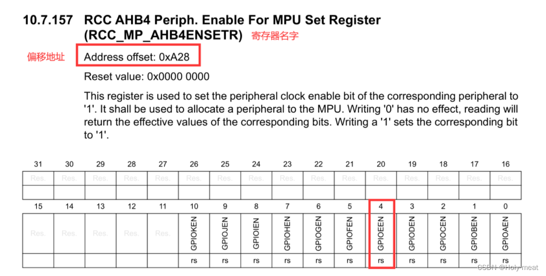
1、RCC_MP_AHB4ENSETR寄存器的功能是使能GPIO组相关控制器;
2、RCC_MP_AHB4ENSETR地址:基地址+偏移地址 =0x5000A28;
2,、使能GPIO组,将第四位置一;
分析GPIO章节
一、寄存器的作用
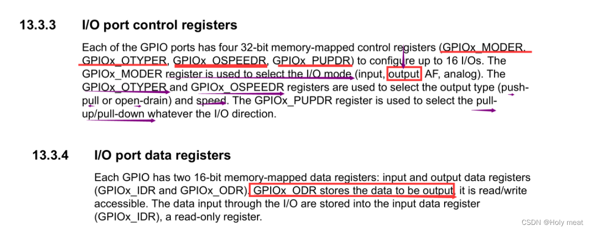
二、各个寄存器分析
基地址+偏移地址
1、GPIOx_MODER
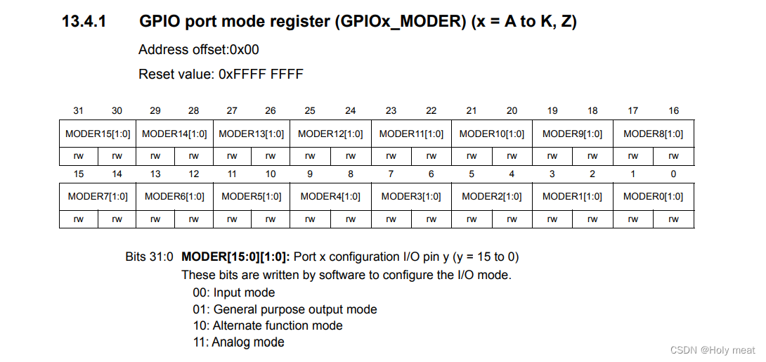
设置PE10引脚为输出模式:将[21:20]置为01;
2、GPIOx_OTYPER
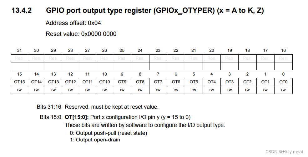
设置PE10引脚为推挽输出类型:将[10]置为0;
3、GPIOx_OSPEEDR

设置PE10引脚为低速输出模式:将[21:20]置为00;
4、GPIOx_PUPDR
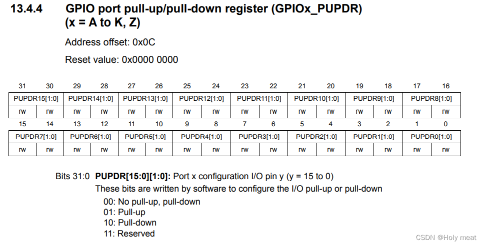
设置PE10引脚为禁止外接上下拉电阻:将[21:20]置为00;
5、GPIOx_ODR
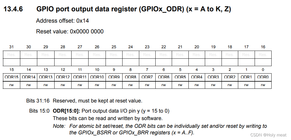
设置PE10引脚输出高低电频:
[10]=0 >>>>低电平LED熄灭
[10]=1 >>>>高电平LED点亮
编写代码
.text
.global _start
_start:
	/**********LED1点灯LED1----->PE10/
LED1_INIT:
	/**************RCC章节*************/
	@1.通过RCC_MP_AHB4ENSETR寄存器设置GPIOE时钟使能 0x50000A28[4] = 1
	ldr r0,=0x50000A28
	ldr r1,[r0]
	orr r1,r1,#(0x1 << 4)
	str r1,[r0]

	/**************GPIO章节************/
	@1.通过GPIOE_MODER寄存器设置PE10引脚为输出模式 0x50006000[21:20] = 01
	ldr r0,=0x50006000
	ldr r1,[r0]
	and r1,r1,#(~(0x3<<20))
	orr r1,r1,#(0x1<<20)
	str r1,[r0]

	@2.通过GPIOE_OTYPER寄存器设置PE10引脚为推晚输出模式 0x50006004[10] = 0
	ldr r0,=0x50006004
	ldr r1,[r0]
	and r1,#(~(0x1<<10))
	str r1,[r0]
	@3.通过GPIOE_OSPEEDR寄存器设置PE10引脚为低速输出模式 0x50006008[21:20] = 00
	ldr r0,=0x50006008
	ldr r1,[r0]
	and r1,#(~(0x3<<20))
	str r1,[r0]
	@4.通过GPIOE_PUPDR寄存器设置PE10引脚禁止上下拉电阻 0x5000600C[21:20] = 00
	ldr r0,=0x5000600C
	ldr r1,[r0]
	and r1,#(~(0x3<<20))
	str r1,[r0]

LED2_INIT:
	@1.通过RCC_MP_AHB4ENSETR寄存器设置GPIOE时钟使能 0x50000A28[5] = 1
	ldr r0,=0x50000A28
	ldr r1,[r0]
	orr r1,r1,#(0x1 << 5)
	str r1,[r0]
	@1.通过GPIOE_MODER寄存器设置PF10引脚为输出模式 0x50007000[21:20] = 01
	ldr r0,=0x50007000
	ldr r1,[r0]
	and r1,r1,#(~(0x3<<20))
	orr r1,r1,#(0x1<<20)
	str r1,[r0]

	@2.通过GPIOE_OTYPER寄存器设置PF10引脚为推晚输出模式 0x50007004[10] = 0
	ldr r0,=0x50007004
	ldr r1,[r0]
	and r1,#(~(0x1<<10))
	str r1,[r0]
	@3.通过GPIOE_OSPEEDR寄存器设置PF10引脚为低速输出模式 0x50007008[21:20] = 00
	ldr r0,=0x50007008
	ldr r1,[r0]
	and r1,#(~(0x3<<20))
	str r1,[r0]
	@4.通过GPIOE_PUPDR寄存器设置PF10引脚禁止上下拉电阻 0x5000700C[21:20] = 00
	ldr r0,=0x5000700C
	ldr r1,[r0]
	and r1,#(~(0x3<<20))
	str r1,[r0]

LED3_INIT:
	@1.通过RCC_MP_AHB4ENSETR寄存器设置GPIOE时钟使能 0x50000A28[4] = 1
	ldr r0,=0x50000A28
	ldr r1,[r0]
	orr r1,r1,#(0x1 << 4)
	str r1,[r0]

	@1.通过GPIOE_MODER寄存器设置PE8引脚为输出模式 0x50006000[17:16] = 01
	ldr r0,=0x50006000
	ldr r1,[r0]
	and r1,r1,#(~(0x3<<16))
	orr r1,r1,#(0x1<<16)
	str r1,[r0]

	@2.通过GPIOE_OTYPER寄存器设置PE8引脚为推晚输出模式 0x50006004[8] = 0
	ldr r0,=0x50006004
	ldr r1,[r0]
	and r1,#(~(0x1<<8))
	str r1,[r0]

	@3.通过GPIOE_OSPEEDR寄存器设置PE10引脚为低速输出模式 0x50006008[17:16] = 00
	ldr r0,=0x50006008
	ldr r1,[r0]
	and r1,#(~(0x3<<16))
	str r1,[r0]
	@4.通过GPIOE_PUPDR寄存器设置PE10引脚禁止上下拉电阻 0x5000600C[17:16] = 00
	ldr r0,=0x5000600C
	ldr r1,[r0]
	and r1,#(~(0x3<<16))
	str r1,[r0]

loop:
	bl LED1_ON
	bl delay_1s
	bl LED1_OFF
	bl delay_1s

	bl LED2_ON
	bl delay_1s
	bl LED2_OFF
	bl delay_1s

	bl LED3_ON
	bl delay_1s
	bl LED3_OFF
	bl delay_1s

	b loop

LED1_ON:
	@1.通过GPIOE_ODR寄存器设置PE10引脚输出高电平 0x50006014[10] = 1
	ldr r0,=0x50006014
	ldr r1,[r0]
	orr r1,r1,#(0x1<<10)
	str r1,[r0]
	mov pc,lr

LED1_OFF:
	@1.通过GPIOE_ODR寄存器设置PE10引脚输出低电平 0x50006014[10] = 0
	ldr r0,=0x50006014
	ldr r1,[r0]
	and r1,r1,#(~(0x1<<10))
	str r1,[r0]
	mov pc,lr

LED2_ON:
	@1.通过GPIOE_ODR寄存器设置PF10引脚输出高电平 0x50007014[10] = 1
	ldr r0,=0x50007014
	ldr r1,[r0]
	orr r1,r1,#(0x1<<10)
	str r1,[r0]
	mov pc,lr

LED2_OFF:
	@1.通过GPIOE_ODR寄存器设置PF10引脚输出低电平 0x50007014[10] = 0
	ldr r0,=0x50007014
	ldr r1,[r0]
	and r1,r1,#(~(0x1<<10))
	str r1,[r0]
	mov pc,lr


LED3_ON:
	@1.通过GPIOE_ODR寄存器设置PE8引脚输出高电平 0x50006014[8] = 1
	ldr r0,=0x50006014
	ldr r1,[r0]
	orr r1,r1,#(0x1<<8)
	str r1,[r0]
	mov pc,lr

LED3_OFF:
	@1.通过GPIOE_ODR寄存器设置PE8引脚输出低电平 0x50006014[8] = 0
	ldr r0,=0x50006014
	ldr r1,[r0]
	and r1,r1,#(~(0x1<<8))
	str r1,[r0]
	mov pc,lr

@ 大概1s的延时函数
delay_1s:
	mov r3, #0x10000000
	mm:
	cmp r3, #0
	subne r3, r3, #1
	bne mm
	mov pc,lr

.end