目标
主要参考《在Unity中创建基于节点的编辑器_嘿嘿-CSDN博客_unity节点编辑器》,一步步学习如何在Unity中制作节点编辑器。
0. 创建窗口
在工程中添加一个MyNodeEditor.cs文件,MyNodeEditor将继承自EditorWindow。
代码内容如下:
using System.Collections;
using System.Collections.Generic;
using UnityEngine;
using UnityEditor;

public class MyNodeEditor : EditorWindow
{
    //在Window菜单下添加一栏 My Node Editor
    [MenuItem("Window/My Node Editor")]
    private static void OpenWindow()
    {
        //获得一个已存在的MyNodeEditor窗口,若没有则创建一个新的:
        MyNodeEditor window = GetWindow<MyNodeEditor>();
        //设置窗口的标题:
        window.titleContent = new GUIContent("My Node Editor");
    }
}
随后,将可以在菜单中找到 “My Node Editor”:
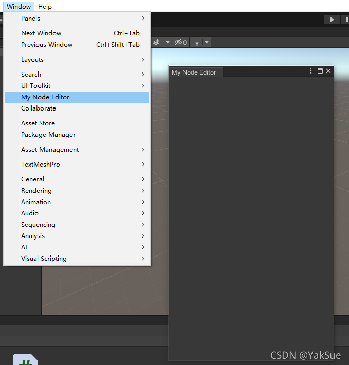
1. 定义节点对象
在工程中添加一个MyNode.cs文件,MyNode不继承任何基类。
当前它只是提供画一个矩形的职责:
using System.Collections;
using System.Collections.Generic;
using UnityEngine;
using UnityEditor;

public class MyNode
{
    public Rect rect;   //节点的矩形范围

    //构造函数
    public MyNode(Vector2 position)
    {
        rect = new Rect(position.x, position.y, 160, 40);
    }

    //绘制自身的图形
    public void Draw()
    {
        GUI.Box(rect, "MyNode");
    }
}
随后,在MyNodeEditor中,定义一个节点列表用于存放所有节点:
private List<MyNode> nodes; //节点列表
然后在其OpenWindow()函数中创建这个对象,并临时加一个测试用节点
//创建节点列表对象
window.nodes = new List<MyNode>();
//临时加一个测试用节点
window.nodes.Add(new MyNode(new Vector2(0, 0)));
最后,调用它的 OnGUI 接口,用于将所有的节点都绘制出来:
//EditorWindow的接口OnGUI:绘制控件调用的接口
private void OnGUI()
{
    DrawNodes();

    if (GUI.changed)
        Repaint();
}

//绘制所有节点
private void DrawNodes()
{
    for (int i = 0; i < nodes.Count; i++)
        nodes[i].Draw();
}
现在,打开MyNodeEditor可以看到一个矩形:

2. 实现“添加节点”功能
首先,在MyNodeEditor中添加处理事件的逻辑,应该在鼠标右键点击后出现一个菜单,然后菜单中有一项是“Add Node”用于在鼠标之处添加节点。代码如下:
//处理事件
private void ProcessEvents(Event e)
{
    switch (e.type)//根据事件类型做判断
    {
        case EventType.MouseDown:   //按下鼠标键
            if (e.button == 1)      //鼠标右键
            {
                //触发菜单
                RightMouseMenu(e.mousePosition);
            }
            break;
    }
}
//鼠标右键菜单:
private void RightMouseMenu(Vector2 mousePosition)
{
    //创建菜单对象
    GenericMenu genericMenu = new GenericMenu();
    //菜单加一项 Add node
    genericMenu.AddItem(new GUIContent("Add node"), false, () => ProcessAddNode(mousePosition));
    //显示菜单
    genericMenu.ShowAsContext();
}
//处理添加节点
private void ProcessAddNode(Vector2 nodePosition)
{
    nodes.Add(new MyNode(nodePosition));
}
随后,在 OnGUI 中运行处理事件的逻辑:
//EditorWindow的接口OnGUI:绘制控件调用的接口
private void OnGUI()
{
    //绘制节点
    DrawNodes();
    //处理事件
    ProcessEvents(Event.current);

    if (GUI.changed)
        Repaint();
}
现在,MyNodeEditor 可以右键添加节点了:
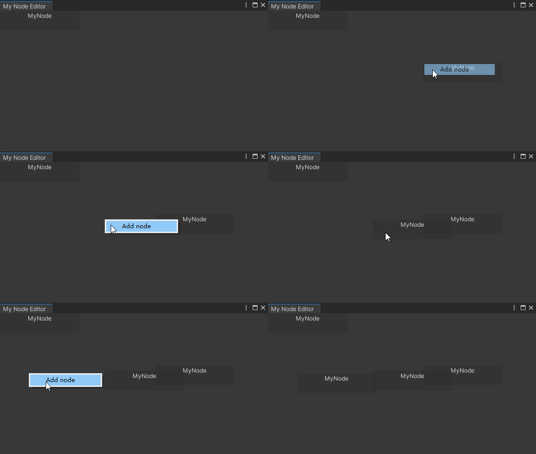
3. 实现“拖拽节点”功能
首先看MyNode。对于他来说,拖拽本身的表现很简单,就是位置加上偏移:
//处理拖拽
public void ProcessDrag(Vector2 delta)
{
    //使自身位置增加偏移
    rect.position += delta;
}
而触发拖拽的逻辑,则由一个Event(事件)来控制。Event将指明鼠标的状态,是按下、松开、拖拽。具体来说:
//此节点处理事件,返回是否发生拖拽
public bool ProcessEvents(Event e)
{
    switch (e.type)
    {
        //鼠标按下:
        case EventType.MouseDown:
            if (e.button == 0)//按下左键
            {
                if (rect.Contains(e.mousePosition)) //是否按在了节点范围内
                    isDragged = true;   //标志着进入拖拽状态

                GUI.changed = true; //提示GUI变化
            }
            break;
        //鼠标松开:
        case EventType.MouseUp:
            isDragged = false;          //标志着离开拖拽状态
            break;
        //鼠标拖拽:
        case EventType.MouseDrag:
            if (e.button == 0 && isDragged) //是否按下鼠标右键且在拖拽状态
            {
                ProcessDrag(e.delta);   //处理拖拽
                e.Use();                //标志着这个事件已经被处理过了,其他GUI元素之后将忽略它
                return true;            //返回true,表示发生了拖拽
            }
            break;
    }
    return false;   //如果最后没有任何拖拽发生,则返回false
}
其中,isDragged是定义在节点中的一个成员变量,它标志着是否在拖拽状态。
private bool isDragged; //标志着是否在拖拽状态
接下来,就是在MyNodeEditor中把这个Event传给每个节点。时机就是MyNodeEditor的ProcessEvents函数中:
//降序处理所有节点的事件(之所以降序是因为后画的节点将显示在更上层)
for (int i = nodes.Count - 1; i >= 0; i--)
{
    //处理每个节点的事件并看是否发生了拖拽
    bool DragHappend = nodes[i].ProcessEvents(e);
    //若发生了拖拽则提示GUI发生变化
    if (DragHappend)
        GUI.changed = true;
}
这样,节点就可以用鼠标左键拖拽了:
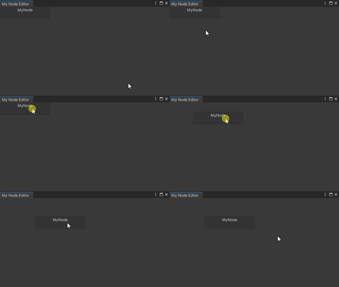
4. 创建“连接点”控件
创建一个新脚本文件ConnectionPoint.cs。ConnectionPoint代表着节点两侧的连接点,它会画一个按钮控件。具体代码如下:
using System.Collections;
using System.Collections.Generic;
using UnityEngine;

//连接点的种类:进、出
public enum ConnectionPointType { In, Out }

//连接点,是节点两侧用于连线的接点
public class ConnectionPoint
{
    public Rect rect;   //矩形范围

    public ConnectionPointType type;    //种类:是进还是出

    public MyNode OwnerNode;    //所归属的节点

    //构造函数
    public ConnectionPoint(MyNode owner, ConnectionPointType type)
    {
        this.OwnerNode = owner;
        this.type = type;

        //矩形范围:
        rect = new Rect
            (0,     //X:之后会根据归属节点重新计算
            0,      //Y:之后会根据归属节点重新计算
            10f,    //宽度
            20f);   //高度
    }

    //绘制图形
    public void Draw()
    {
        //连接点的Y值应在所归属的节点的中间:
        rect.y = OwnerNode.rect.y + (OwnerNode.rect.height * 0.5f) - rect.height * 0.5f;

        //连接点的X值根据种类区分:
        switch (type)
        {
            case ConnectionPointType.In:    //对于进的连接点,绘制在节点的左侧:
                rect.x = OwnerNode.rect.x - rect.width;
                break;

            case ConnectionPointType.Out:   //对于出的连接点,绘制在节点的右侧:
                rect.x = OwnerNode.rect.x + OwnerNode.rect.width;
                break;
        }

        //绘制按钮
        GUI.Button(rect, "");
    }
}
然后,在MyNode中,需要定义两侧连接点成员:
public ConnectionPoint inPoint;     //连接点:进
public ConnectionPoint outPoint;    //连接点:出
在构造函数中,创建这两个对象:
//创建进和出的连接点
inPoint = new ConnectionPoint(this, ConnectionPointType.In);
outPoint = new ConnectionPoint(this, ConnectionPointType.Out);
在绘制函数,也就是Draw()中,添加对这两个连接点的绘制调用:
public void Draw()
{
    //绘制自身:
    GUI.Box(rect, "MyNode");
    //绘制两个连接点:
    inPoint.Draw();
    outPoint.Draw();
}
随后,就可以在节点两侧看到连接点按钮了:
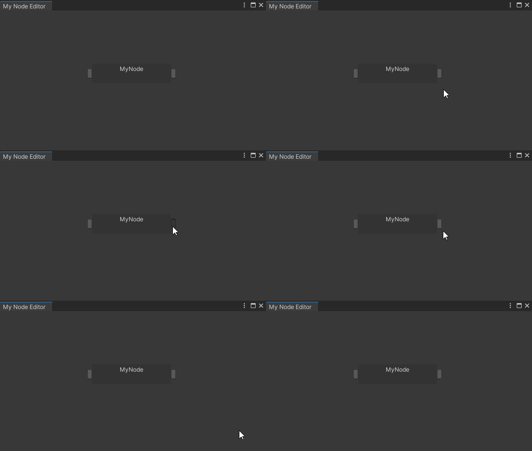
5. 创建“连接线”对象
创建一个新的脚本文件Connection.cs。Connection将代表连接线,其功能很简单,就是画出给定两个连接点之间的曲线:
using System.Collections;
using System.Collections.Generic;
using UnityEngine;
using UnityEditor;

//连接点之间的连线
public class Connection
{
    public ConnectionPoint inPoint;     //进点
    public ConnectionPoint outPoint;    //出点

    //构造函数
    public Connection(ConnectionPoint inPoint, ConnectionPoint outPoint)
    {
        this.inPoint = inPoint;
        this.outPoint = outPoint;
    }

    public void Draw()
    {
        Handles.DrawBezier(     //绘制通过给定切线的起点和终点的纹理化贝塞尔曲线
        inPoint.rect.center,    //startPosition	贝塞尔曲线的起点。
        outPoint.rect.center,   //endPosition	贝塞尔曲线的终点。
        inPoint.rect.center + Vector2.left * 50f,   //startTangent	贝塞尔曲线的起始切线。
        outPoint.rect.center - Vector2.left * 50f,  //endTangent	贝塞尔曲线的终点切线。
        Color.white,        //color	    要用于贝塞尔曲线的颜色。
        null,               //texture	要用于绘制贝塞尔曲线的纹理。
        2f                  //width	    贝塞尔曲线的宽度。
        );
    }
}
而在MyNodeEditor中,需要创建一个列表来容纳当前所有的连线:
private List<Connection> connections; //连接列表
然后需要一个函数来绘制所有的连线,即调用他们的Draw函数:
//绘制所有的连线
private void DrawConnections()
{
    for (int i = 0; i < connections.Count; i++)
        connections[i].Draw();
}
当然,此函数需要在OnGUI中调用:
//EditorWindow的接口OnGUI:绘制控件调用的接口
private void OnGUI()
{
    //绘制节点和连线
    DrawNodes();
    DrawConnections();
...
}
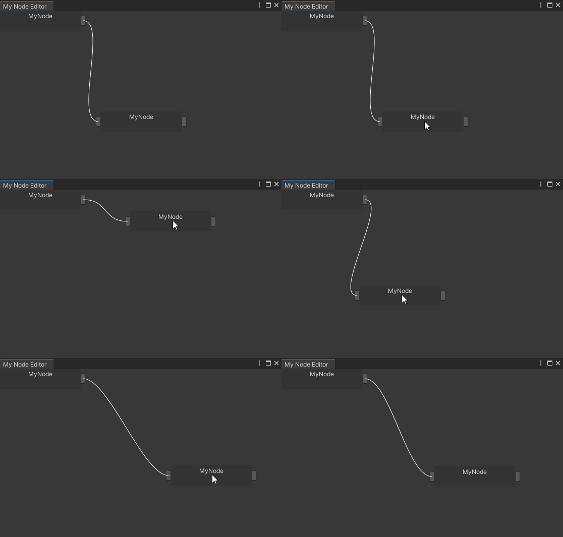
为了测试,我在初始就加了些节点和连线。
另外,我将之前在OpenWindow()中的一些初始化用的函数移动到了OnEnable函数中,修改后代码如下:
//在Window菜单下添加一栏 My Node Editor
[MenuItem("Window/My Node Editor")]
private static void OpenWindow()
{
    //获得一个已存在的MyNodeEditor窗口,若没有则创建一个新的:
    MyNodeEditor window = GetWindow<MyNodeEditor>();
}

//EditorWindow的接口OnEnable:当对象加载时调用此函数
private void OnEnable()
{
    //设置窗口的标题:
    titleContent = new GUIContent("My Node Editor");

    //创建节点列表对象
    nodes = new List<MyNode>();
    //创建连接列表对象
    connections = new List<Connection>();

    //临时加些测试:
    {
        //临时加一个测试用节点
        MyNode n1 = new MyNode(new Vector2(0, 0));
        nodes.Add(n1);
        //临时加第二个测试用节点
        MyNode n2 = new MyNode(new Vector2(200, 200));
        nodes.Add(n2);

        //临时加一个测试的连线
        connections.Add(new Connection(n2.inPoint, n1.outPoint));
    }
}
现在,打开窗口后会看到两个节点并有连线了:
6. 实现“添加连线”功能
“添加连线”需要两个连接点的配合。因此,可以在MyNodeEditor中记录一个当前所选的连接点:
public ConnectionPoint SelectingPoint; //记录正在选择的点,用于判断之后是否会发生连接
而对于连接点,它在调用GUI.Button时,不仅执行了绘制按钮的命令,也将返回按钮是否被按下。因此可以在这里做连线的逻辑:(对于连接点的OwnerWindow指针,则就是在构造函数中传入了,为此添加了一些零碎的代码,省略细节)
//绘制按钮
if(GUI.Button(rect, ""))//按钮被按下后:
{
    //若窗口没有任何选择点,则表示这是选择的第一个点
    if (OwnerWindow.SelectingPoint == null)
        OwnerWindow.SelectingPoint = this;
    else    //否则,窗口中已经选择了一个连接点了
    {
        //若先前所选的连接点的方向和现在的点不一样,则可以创建连接
        if (OwnerWindow.SelectingPoint.type!=this.type)
        {
            //根据自己的类型来决定创建连接时参数的顺序
            if (this.type == ConnectionPointType.In)
                OwnerWindow.connections.Add(new Connection(this, OwnerWindow.SelectingPoint));
            else
                OwnerWindow.connections.Add(new Connection(OwnerWindow.SelectingPoint, this));

            //连接创建结束后将SelectingPoint置为空
            OwnerWindow.SelectingPoint = null;
        }
    }
}
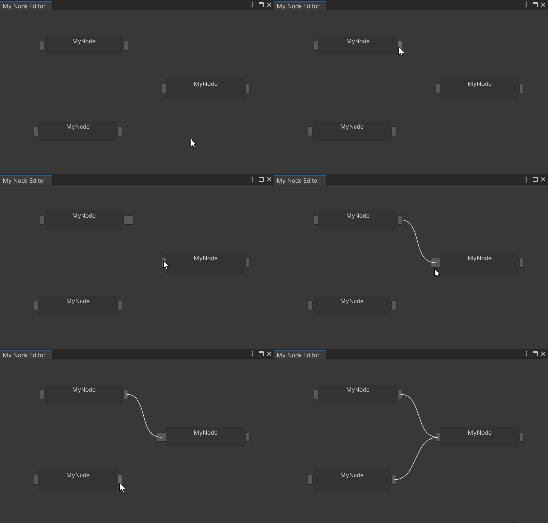
另外,为了能区分出所选的连接点是哪个,我还添加了一个逻辑:将所选的连接点的宽度稍微变长一些:
//如果是当前所选的连接点,则稍微变长一些来区分
rect.width = (OwnerWindow.SelectingPoint == this) ? 20 : 10;
现在,可以有连线功能了:
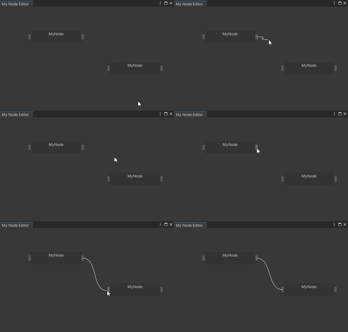
7. 绘制“待连接线”
当所选一个连接点时,如果能画出一条连接鼠标的线,则会有较好的提示作用。为此需要增加一个函数:
//绘制待连接线
private void DrawPendingConnection(Event e)
{
    if(SelectingPoint!=null)//如果已经选择了一个连接点,则画出待连接的线
    {
        //贝塞尔曲线的起点,根据已选则点的方向做判断:
        Vector3 startPosition = (SelectingPoint.type == ConnectionPointType.In) ? SelectingPoint.rect.center : e.mousePosition;
        Vector3 endPosition = (SelectingPoint.type == ConnectionPointType.In) ? e.mousePosition : SelectingPoint.rect.center;

        Handles.DrawBezier(     //绘制通过给定切线的起点和终点的纹理化贝塞尔曲线
        startPosition,
        endPosition,
        startPosition + Vector3.left * 50f, //startTangent	贝塞尔曲线的起始切线。
        endPosition - Vector3.left * 50f,   //endTangent	贝塞尔曲线的终点切线。
        Color.white,        //color	    要用于贝塞尔曲线的颜色。
        null,               //texture	要用于绘制贝塞尔曲线的纹理。
        2f                  //width	    贝塞尔曲线的宽度。
        );

        GUI.changed = true;
    }
}
将此函数在OnGUI中调用:
//EditorWindow的接口OnGUI:绘制控件调用的接口
private void OnGUI()
{
...
    //绘制待连接线
    DrawPendingConnection(Event.current);
...
}
另外,在空白处按下鼠标左键的时候,希望能取消所选的连接点,为此,需要在 ProcessEvents 中添加对其的判断:
//处理事件
private void ProcessEvents(Event e)
{
    switch (e.type)//根据事件类型做判断
    {
        case EventType.MouseDown:   //按下鼠标键
...
            if (e.button == 0)  //按下鼠标左键
            {
                SelectingPoint = null;//清空当前所选的连接点
            }
            break;
    }
...
}
(此外,由于此连接线已经提示了所选的连接点,所以上一步中将所选连接点宽度稍微变长的操作不再需要了)
8. 改变控件风格
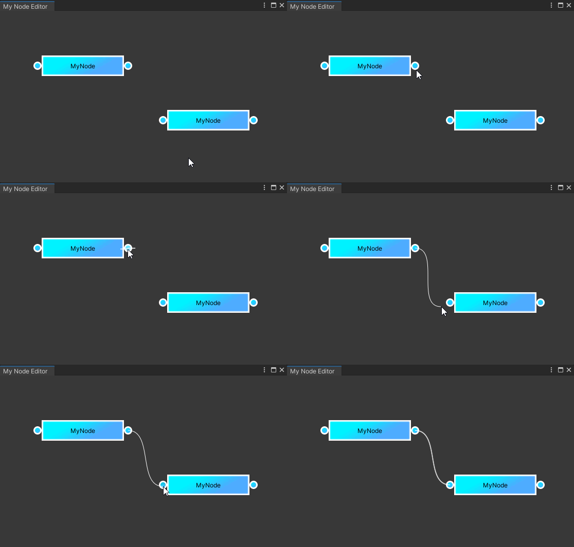
控件风格是由 GUIStyle 指定的。它指定了不同状态(例如,当鼠标悬停在控件上时)的字体和贴图等等细节。上面绘制节点时调用的 GUI.Box 以及绘制连接点调用的GUI.Button都可指明GUIStyle参数。
GUIStyle是相对全局的,不需要每个控件都创建一个,于是我选择在MyNodeEditor中创建并记录下来,待之后分配给新的节点与连接点控件:
//记录一些GUIStyle
GUIStyle style_Node;            //节点的GUI风格
GUIStyle style_Point;           //连接点的GUI风格
我做出了一些控件图片,然后放在工程目录的Assets文件夹下

然后在MyNodeEditor的OnEnable中创建 GUIStyle 并将图片指定给各个状态:
//初始化一些GUIStyle
{
    //节点的风格:
    style_Node = new GUIStyle();
    //normal:	    正常显示组件时的渲染设置
    style_Node.normal.background = EditorGUIUtility.Load("Assets/node.png") as Texture2D;
    //alignment:	文本对齐方式
    style_Node.alignment = TextAnchor.MiddleCenter;//中心

    //连接点的风格:
    style_Point = new GUIStyle();
    //normal:       正常显示组件时的渲染设置
    style_Point.normal.background = EditorGUIUtility.Load("Assets/point_normal.png") as Texture2D;
    //active:       按下控件时的渲染设置。
    style_Point.active.background = EditorGUIUtility.Load("Assets/point_active.png") as Texture2D;
    //hover:        鼠标悬停在控件上时的渲染设置。
    style_Point.hover.background = EditorGUIUtility.Load("Assets/point_hover.png") as Texture2D;
}
接下来,这两个 GUIStyle 将在节点和连接点的构造函数中被传入,并在GUI.Box和GUI.Button时使用。(代码略)
(另外,我还稍微调整了下连接点的位置,以及连接线的宽度)
9. 实现“选择节点”功能
为了标志节点是否被选择,需要在MyNode中添加一个成员:
private bool isSelected;//标志着是否正在被选择
判断是否被选择时机很简单,就是在鼠标左键按下时——若点中了自己则自己就是被选中的,否则就不是:
//此节点处理事件,返回是否发生拖拽
public bool ProcessEvents(Event e)
{
    switch (e.type)
    {
        //鼠标按下:
        case EventType.MouseDown:
            if (e.button == 0)//按下左键
            {
                if (rect.Contains(e.mousePosition)) //是否按在了节点范围内
                {
                    isDragged = true;   //标志着进入拖拽状态
                    isSelected = true;
                }
                else
                {
                    isSelected = false;
                }
...
            }
            break;
...
    }
...
}
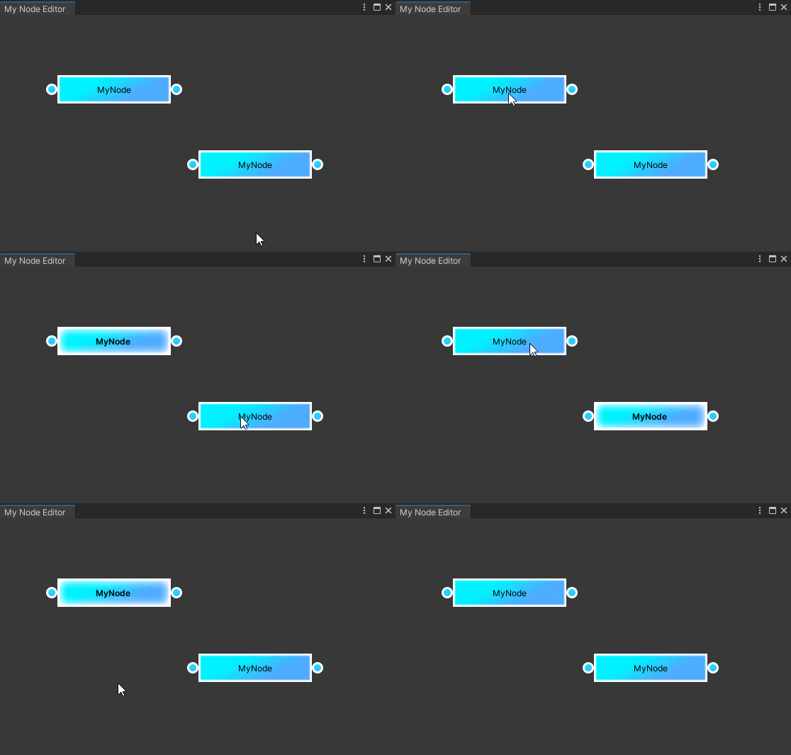
而当节点进入选择状态时,希望能换一个GUIStyle来提示自己被选择,因此节点现在需要两个GUIStyle了:
private GUIStyle style;         //节点正常情况下的风格
private GUIStyle style_select;  //节点被选择下的风格
而新的 GUIStyle 自然也是在MyNodeEditor中创建:
//节点在选择状态下的风格:
style_Node_select = new GUIStyle();
//normal:	    正常显示组件时的渲染设置
style_Node_select.normal.background = EditorGUIUtility.Load("Assets/node_select.png") as Texture2D;
//alignment:	文本对齐方式
style_Node_select.alignment = TextAnchor.MiddleCenter;//中心
//fontStyle:   要使用的字体样式
style_Node_select.fontStyle = FontStyle.Bold;//粗体
随后在MyNode的构造函数中传入。
而MyNode在绘制时则根据isSelected的值调整自己的GUIStyle:
//绘制自身:
GUI.Box(rect, "MyNode", isSelected ? style_select : style);
10. 实现“删除节点”功能
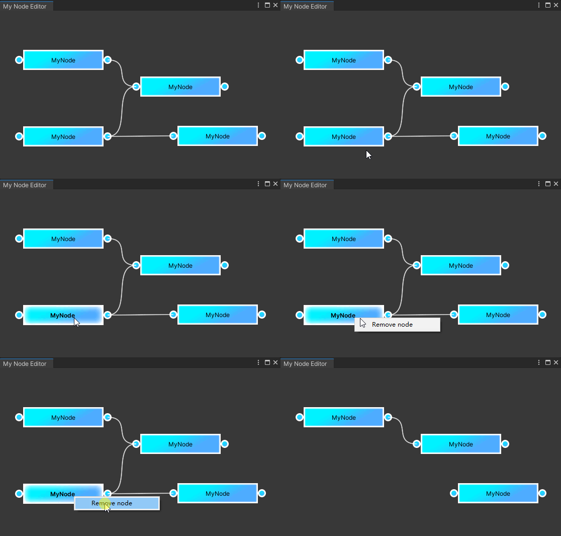
删除节点需要注意的是,删除的时候还需要判断哪些连接和它有关,要一并删除。
我将删除节点的函数放在了MyNodeEditor中:
//处理移除节点
public void ProcessRemoveNode(MyNode node)
{
    //收集“待删除连接列表”
    List<Connection> connectionsToRemove = new List<Connection>();

    //遍历所有的连接,若连接的入点或出点是属于要删除的节点的,则将其添加到“待删除连接列表”中
    for (int i = 0; i < connections.Count; i++)
    {
        if (connections[i].inPoint == node.inPoint || connections[i].outPoint == node.outPoint)
            connectionsToRemove.Add(connections[i]);
    }

    //删除“待删除连接列表”中所有连接
    for (int i = 0; i < connectionsToRemove.Count; i++)
        connections.Remove(connectionsToRemove[i]);

    connectionsToRemove = null;

    //移除节点
    nodes.Remove(node);
}
而触发它的时机和“添加节点”类似,都是右键菜单。只不过这次需要在MyNode中判断,并且在此节点是所选节点的情况下才触发:
 //此节点处理事件,返回是否发生拖拽
public bool ProcessEvents(Event e)
{
    switch (e.type)
    {
        //鼠标按下:
        case EventType.MouseDown:
...
            if (e.button == 1)//按下右键
            {
                //被选择且鼠标在节点范围内
                if(isSelected && rect.Contains(e.mousePosition))
                {
                    RightMouseMenu();
                    e.Use();
                }
            }
            break;
...
    }
...
}
而RightMouseMenu()中将负责生成一个菜单并调用之前的ProcessRemoveNode函数:
//鼠标右键菜单:
private void RightMouseMenu()
{
    //创建菜单对象
    GenericMenu genericMenu = new GenericMenu();
    //菜单加一项 Remove node,它将调用节点窗口的ProcessRemoveNode函数
    genericMenu.AddItem(new GUIContent("Remove node"), false, () => OwnerWindow.ProcessRemoveNode(this));
    //显示菜单
    genericMenu.ShowAsContext();
}
11. 实现“删除连线”功能
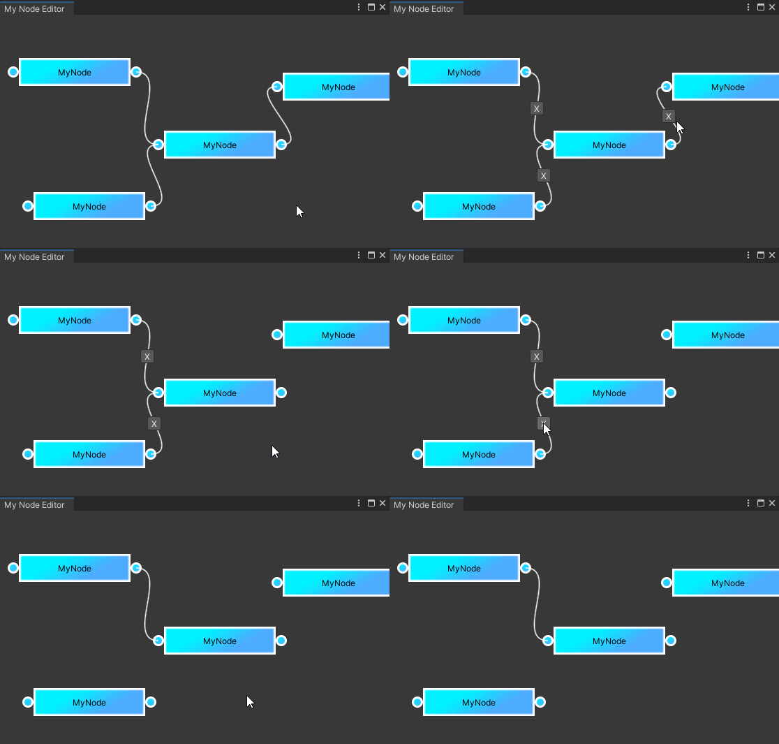
删除连线的方式,原教程是在连线上放一个按钮点击可以删除。虽然有些影响美观,但这确实是一种简单直接的方式,因此我决定沿用这一做法,但稍微加一些改动——仅在按住Y键时才显示菜单。
所以,需要在MyNodeEditor中增加一个变量用于表示是否进入移除连线模式
public bool isRemoveConnectionMode; //标志着是否进入移除连线模式
而其变化的逻辑和鼠标事件一样,也在ProcessEvents中做判断:
private void ProcessEvents(Event e)
{
    switch (e.type)//根据事件类型做判断
    {
...
        case EventType.KeyDown: //按下键盘
            if (e.keyCode == KeyCode.Y)//是Y键
            {
                isRemoveConnectionMode = true;  //进入移除连线模式
                GUI.changed = true;             //提示需要刷新GUI
            }
            break;
        case EventType.KeyUp: //松开键盘
            if (e.keyCode == KeyCode.Y)//是Y键
            {
                isRemoveConnectionMode = false; //离开移除连线模式
                GUI.changed = true;             //提示需要刷新GUI
            }
            break;
    }
...
}
随后,在Connection中就可以根据此变量来判断是否该显示按钮了:
if(OwnerWindow.isRemoveConnectionMode)//仅在移除连线模式下才显示移除连线的按钮
{
    Vector2 buttonSize = new Vector2(20, 20);//按钮的尺寸

    //连线的中心,即按钮的位置
    Vector2 LineCenter = (inPoint.rect.center + outPoint.rect.center) / 2;
    //绘制按钮,按下时移除自己
    if (GUI.Button(new Rect(LineCenter - buttonSize / 2, buttonSize), "X"))
        OwnerWindow.connections.Remove(this);//移除自己
}
12. 实现“拖拽画布”功能
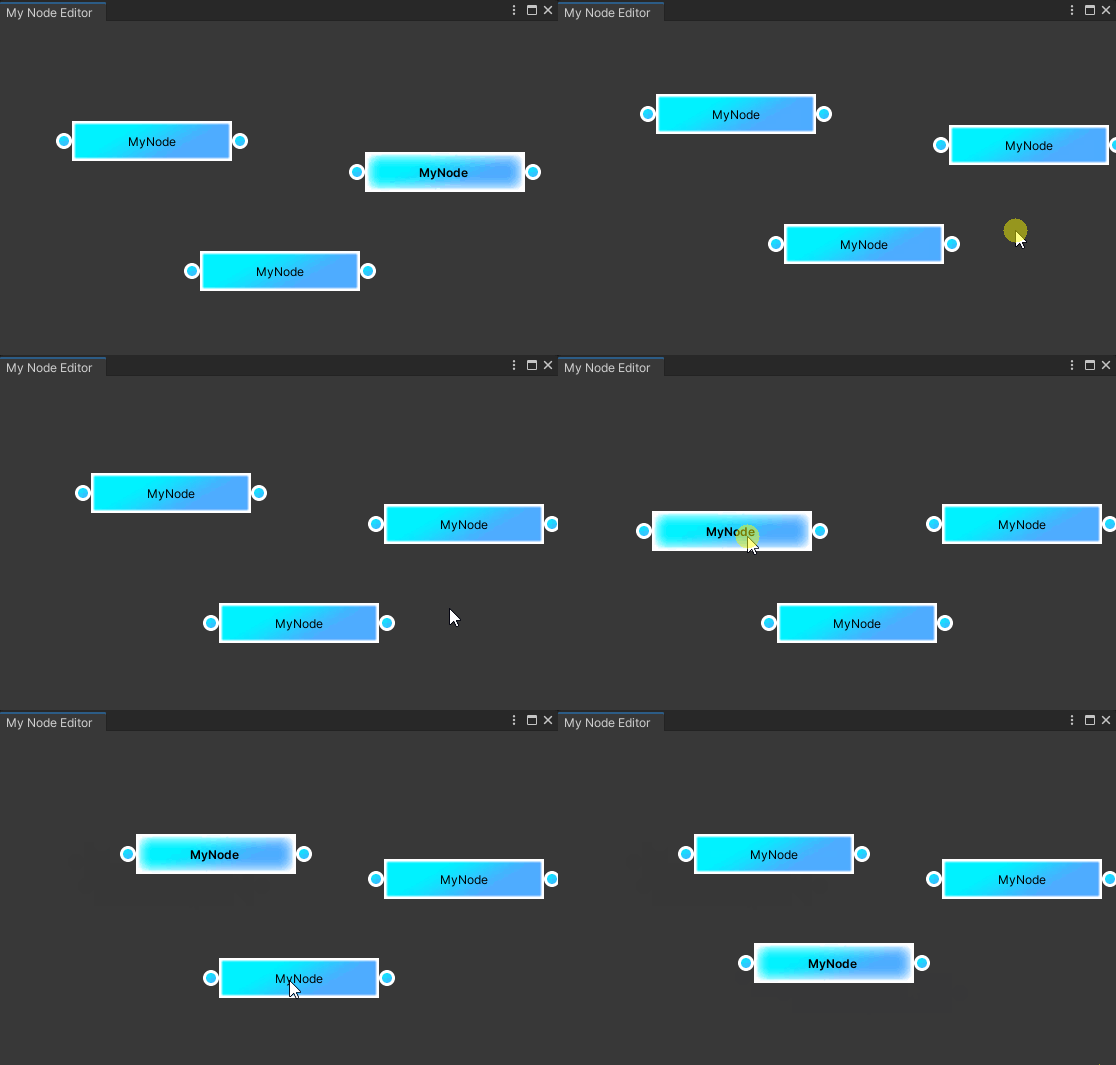
拖拽画布其实就是再MyNodeEditor中拖拽所有节点:
//拖拽所有节点(拖拽画布)
private void DragAllNodes(Vector2 delta)
{
    for (int i = 0; i < nodes.Count; i++)
        nodes[i].ProcessDrag(delta);
}
接下来是判断何时发生了拖拽,很自然想到的是,依旧通过 EventType.MouseDrag 来判断:
 private void ProcessEvents(Event e)
    {
        switch (e.type)//根据事件类型做判断
        {
...
            case EventType.MouseDrag:   //鼠标拖拽
                if(e.button == 0)       //鼠标左键
                {
                    DragAllNodes(e.delta);  //拖拽所有节点(拖拽画布)
                    GUI.changed = true;     //提示需要刷新GUI
                }
                break;
        }
    }
然而问题是,节点的拖拽也是同样的判断,那么该如何区分“节点的拖拽”与“画布的拖拽”呢?
关键的注意点是:要先处理节点的事件,再处理MyNodeEditor自身的事件。因为如果节点接受到了拖拽的信息,则会调用Event.Use:

这样,之后的MyNodeEditor自身就不会再处理拖拽事件了。
13. 绘制背景网格
绘制背景网格其实就是基于当前的窗口画若干条直线。
由于我们还有拖拽画布的功能,所以背景网格也需要知道拖拽的偏移才能画出正确位置的网格。
private Vector2 GridOffset; //画布网格的偏移
此值会在拖拽时一并修改:
case EventType.MouseDrag:   //鼠标拖拽
     if(e.button == 0)       //鼠标左键
     {
         ...
         GridOffset += e.delta;  //增加画布网格的偏移
         ...
     }
绘制网格的代码如下:
//绘制画布网格
//gridSpacing:  格子间距
//gridOpacity:  网格线不透明度
//gridColor:    网格线颜色
private void DrawGrid(float gridSpacing, float gridOpacity, Color gridColor)
{
    //宽度分段
    int widthDivs = Mathf.CeilToInt(position.width / gridSpacing);
    //高度分段
    int heightDivs = Mathf.CeilToInt(position.height / gridSpacing);

    Handles.BeginGUI();//在 3D Handle GUI 内开始一个 2D GUI 块。
    {
        //设置颜色:
        Handles.color = new Color(gridColor.r, gridColor.g, gridColor.b, gridOpacity);

        //单格的偏移,算是GridOffset的除余
        Vector3 gridOffset = new Vector3(GridOffset.x % gridSpacing, GridOffset.y % gridSpacing, 0);

        //绘制所有的竖线
        for (int i = 0; i < widthDivs; i++)
        {
            Handles.DrawLine(
                new Vector3(gridSpacing * i, 0 - gridSpacing, 0) + gridOffset,                  //起点
                new Vector3(gridSpacing * i, position.height + gridSpacing, 0f) + gridOffset);  //终点
        }
        //绘制所有的横线
        for (int j = 0; j < heightDivs; j++)
        {
            Handles.DrawLine(
                new Vector3(0 - gridSpacing, gridSpacing * j, 0) + gridOffset,                  //起点
                new Vector3(position.width + gridSpacing, gridSpacing * j, 0f) + gridOffset);   //终点
        }

        //重设颜色
        Handles.color = Color.white;
    }
    Handles.EndGUI(); //结束一个 2D GUI 块并返回到 3D Handle GUI。
}
而在OnGUI()中将调用两次,第二次是更宽的更明显的网格:
//EditorWindow的接口OnGUI:绘制控件调用的接口
private void OnGUI()
{
    //绘制背景画布网格
    DrawGrid(20, 0.2f, Color.gray);
    DrawGrid(100, 0.4f, Color.gray);
...
}
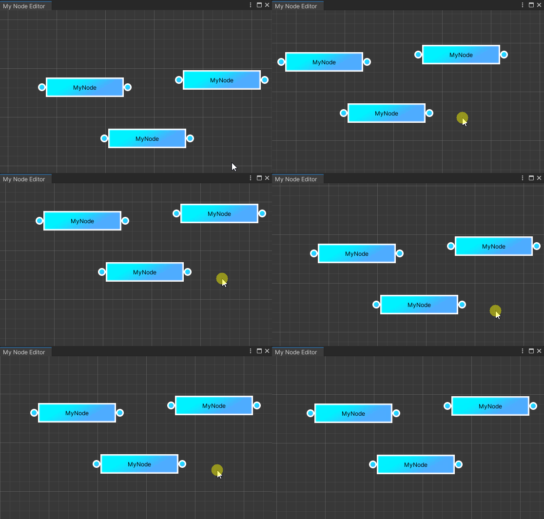
最终代码
代码与图片资源详见GIT:https://codechina.csdn.net/u013412391/unitytestnodeeditor.git
对于每一个步骤都可见提交历史:

