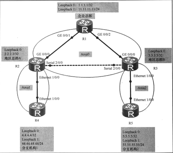
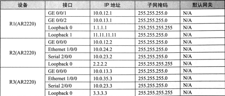
实验内容:

实验拓扑:

实验编址表:


实验配置:
一、配置ospf路由协议
[R1]router id 1.1.1.1
[R1]ospf 1
[R1-ospf-1]area 0
[R1-ospf-1-area-0.0.0.0]network 1.1.1.1 0.0.0.0
[R1-ospf-1-area-0.0.0.0]network 10.0.12.1 0.0.0.0
[R1-ospf-1-area-0.0.0.0]network 10.0.13.1 0.0.0.0
[R1-ospf-1-area-0.0.0.0]network 11.11.11.11 0.0.0.0
[R2]router id 2.2.2.2
[R2]ospf 1
[R2-ospf-1]area 0
[R2-ospf-1-area-0.0.0.0]network 10.0.12.2 0.0.0.0
[R2-ospf-1-area-0.0.0.0]network 10.0.23.2 0.0.0.0
[R2-ospf-1-area-0.0.0.0]network 2.2.2.2 0.0.0.0
[R2-ospf-1]area 1
[R2-ospf-1]network 10.0.24.2 0.0.0.0
[R3]router id 3.3.3.3
[R3]ospf 1
[R3-ospf-1]area 0
[R3-ospf-1-area-0.0.0.0]network 10.0.13.3 0.0.0.0
[R3-ospf-1-area-0.0.0.0]network 10.0.23.3 0.0.0.0
[R3-ospf-1-area-0.0.0.0]network 3.3.3.3 0.0.0.0
[R3-ospf-1]area 2
[R3-ospf-1-area-0.0.0.2]network 10.0.35.3 0.0.0.0
[R4]router id 4.4.4.4
[R4]ospf 1
[R4-ospf-1]area 1
[R4-ospf-1-area-0.0.0.1]network 10.0.24.4 0.0.0.0
[R4-ospf-1-area-0.0.0.1]network 4.4.4.4 0.0.0.0
[R4-ospf-1-area-0.0.0.1]network 44.44.44.44 0.0.0.0
[R5]router id 5.5.5.5
[R5]ospf 1
[R5-ospf-1]area 2
[R5-ospf-1-area-0.0.0.2]network 10.0.35.5 0.0.0.0
[R5-ospf-1-area-0.0.0.2]network 5.5.5.5 0.0.0.0
[R5-ospf-1-area-0.0.0.2]network 55.55.55.55 0.0.0.0
配置完成后,查看R1、R2、R3上ospf邻居的建立情况。
[R1]display ospf peer brief

	 OSPF Process 1 with Router ID 1.1.1.1
		  Peer Statistic Information
 ----------------------------------------------------------------------------
 Area Id          Interface                        Neighbor id      State
 0.0.0.0          GigabitEthernet0/0/1             2.2.2.2          Full
 0.0.0.0          GigabitEthernet0/0/2             3.3.3.3          Full
 ----------------------------------------------------------------------------
[R2]display ospf peer brief

	 OSPF Process 1 with Router ID 2.2.2.2
		  Peer Statistic Information
 ----------------------------------------------------------------------------
 Area Id          Interface                        Neighbor id      State
 0.0.0.0          GigabitEthernet0/0/0             1.1.1.1          Full
 0.0.0.0          Serial2/0/0                      3.3.3.3          Full
 0.0.0.1          Ethernet1/0/0                    4.4.4.4          Full
 ----------------------------------------------------------------------------
[R3]display ospf peer brief

	 OSPF Process 1 with Router ID 3.3.3.3
		  Peer Statistic Information
 ----------------------------------------------------------------------------
 Area Id          Interface                        Neighbor id      State
 0.0.0.0          GigabitEthernet0/0/0             1.1.1.1          Full
 0.0.0.0          Serial2/0/0                      2.2.2.2          Full
 0.0.0.2          Ethernet1/0/0                    5.5.5.5          Full
 ----------------------------------------------------------------------------
可以看到,ospf邻居状态都为FULL,表明各邻居关系都已经成功建立。
查看R1路由表:
<R1>display ip routing-table
Route Flags: R - relay, D - download to fib
------------------------------------------------------------------------------
Routing Tables: Public
         Destinations : 23       Routes : 24

Destination/Mask    Proto   Pre  Cost      Flags NextHop         Interface

        1.1.1.1/32  Direct  0    0           D   127.0.0.1       LoopBack0
        2.2.2.2/32  OSPF    10   1           D   10.0.12.2       GigabitEthernet
0/0/1
        3.3.3.3/32  OSPF    10   1           D   10.0.13.3       GigabitEthernet
0/0/2
        4.4.4.4/32  OSPF    10   2           D   10.0.12.2       GigabitEthernet
0/0/1
        5.5.5.5/32  OSPF    10   2           D   10.0.13.3       GigabitEthernet
0/0/2
      10.0.12.0/24  Direct  0    0           D   10.0.12.1       GigabitEthernet
0/0/1
      10.0.12.1/32  Direct  0    0           D   127.0.0.1       GigabitEthernet
0/0/1
    10.0.12.255/32  Direct  0    0           D   127.0.0.1       GigabitEthernet
0/0/1
      10.0.13.0/24  Direct  0    0           D   10.0.13.1       GigabitEthernet
0/0/2
      10.0.13.1/32  Direct  0    0           D   127.0.0.1       GigabitEthernet
0/0/2
    10.0.13.255/32  Direct  0    0           D   127.0.0.1       GigabitEthernet
0/0/2
      10.0.23.0/24  OSPF    10   49          D   10.0.13.3       GigabitEthernet
0/0/2
                    OSPF    10   49          D   10.0.12.2       GigabitEthernet
0/0/1
      10.0.24.0/24  OSPF    10   2           D   10.0.12.2       GigabitEthernet
0/0/1
      10.0.35.0/24  OSPF    10   2           D   10.0.13.3       GigabitEthernet
0/0/2
     11.11.11.0/24  Direct  0    0           D   11.11.11.11     LoopBack1
    11.11.11.11/32  Direct  0    0           D   127.0.0.1       LoopBack1
   11.11.11.255/32  Direct  0    0           D   127.0.0.1       LoopBack1
    44.44.44.44/32  OSPF    10   2           D   10.0.12.2       GigabitEthernet
0/0/1
    55.55.55.55/32  OSPF    10   2           D   10.0.13.3       GigabitEthernet
0/0/2
      127.0.0.0/8   Direct  0    0           D   127.0.0.1       InLoopBack0
      127.0.0.1/32  Direct  0    0           D   127.0.0.1       InLoopBack0
127.255.255.255/32  Direct  0    0           D   127.0.0.1       InLoopBack0
255.255.255.255/32  Direct  0    0           D   127.0.0.1       InLoopBack0
可以看到企业总部路由器R1已经获得了其他路由器的接口所再网段的路由了。
查看R4的路由表:
<R4>display ip routing-table
Route Flags: R - relay, D - download to fib
------------------------------------------------------------------------------
Routing Tables: Public
         Destinations : 21       Routes : 21

Destination/Mask    Proto   Pre  Cost      Flags NextHop         Interface

        1.1.1.1/32  OSPF    10   2           D   10.0.24.2       Ethernet1/0/0
        2.2.2.2/32  OSPF    10   1           D   10.0.24.2       Ethernet1/0/0
        3.3.3.3/32  OSPF    10   3           D   10.0.24.2       Ethernet1/0/0
        4.4.4.4/32  Direct  0    0           D   127.0.0.1       LoopBack0
        5.5.5.5/32  OSPF    10   4           D   10.0.24.2       Ethernet1/0/0
      10.0.12.0/24  OSPF    10   2           D   10.0.24.2       Ethernet1/0/0
      10.0.13.0/24  OSPF    10   3           D   10.0.24.2       Ethernet1/0/0
      10.0.23.0/24  OSPF    10   49          D   10.0.24.2       Ethernet1/0/0
      10.0.24.0/24  Direct  0    0           D   10.0.24.4       Ethernet1/0/0
      10.0.24.4/32  Direct  0    0           D   127.0.0.1       Ethernet1/0/0
    10.0.24.255/32  Direct  0    0           D   127.0.0.1       Ethernet1/0/0
      10.0.35.0/24  OSPF    10   4           D   10.0.24.2       Ethernet1/0/0
    11.11.11.11/32  OSPF    10   2           D   10.0.24.2       Ethernet1/0/0
     44.44.44.0/24  Direct  0    0           D   44.44.44.44     LoopBack1
    44.44.44.44/32  Direct  0    0           D   127.0.0.1       LoopBack1
   44.44.44.255/32  Direct  0    0           D   127.0.0.1       LoopBack1
    55.55.55.55/32  OSPF    10   4           D   10.0.24.2       Ethernet1/0/0
      127.0.0.0/8   Direct  0    0           D   127.0.0.1       InLoopBack0
      127.0.0.1/32  Direct  0    0           D   127.0.0.1       InLoopBack0
127.255.255.255/32  Direct  0    0           D   127.0.0.1       InLoopBack0
255.255.255.255/32  Direct  0    0           D   127.0.0.1       InLoopBack0
可以看到分支机构1的路由器R4已经获得了企业总部、地区总部以及分支机构2的所有网段的路由。至此所有分支机构和企业总部及地区总部的路由已经实现了互通,相互之间可以进行通信。
二、查看DR/BDR选举情况。
DR/BDR的选举规则:
1、比较路由器接口的DR优先级,优先级最高的为DR,次之者为BDR,其余的为DRother。DR优先级默认值为1,如果为0,则表示不选与选举。
2、如果接口的DR优先级相同,则比较路由器的Router-ID,数值最大的为DR,次之者为BDR,其余为DRother。
在R1、R2上查看DR/BDR的选举情况:
<R1>display ospf interface

	 OSPF Process 1 with Router ID 1.1.1.1
		 Interfaces

 Area: 0.0.0.0          (MPLS TE not enabled)
 IP Address      Type         State    Cost    Pri   DR              BDR
 10.0.12.1       Broadcast    BDR      1       1     10.0.12.2       10.0.12.1
 10.0.13.1       Broadcast    BDR      1       1     10.0.13.3       10.0.13.1
 1.1.1.1         P2P          P-2-P    0       1     0.0.0.0         0.0.0.0
 11.11.11.11     P2P          P-2-P    0       1     0.0.0.0         0.0.0.0
<R2>display ospf interface

	 OSPF Process 1 with Router ID 2.2.2.2
		 Interfaces

 Area: 0.0.0.0          (MPLS TE not enabled)
 IP Address      Type         State    Cost    Pri   DR              BDR
 10.0.12.2       Broadcast    DR       1       1     10.0.12.2       10.0.12.1
 2.2.2.2         P2P          P-2-P    0       1     0.0.0.0         0.0.0.0
 10.0.23.2       P2P          P-2-P    48      1     0.0.0.0         0.0.0.0

 Area: 0.0.0.1          (MPLS TE not enabled)
 IP Address      Type         State    Cost    Pri   DR              BDR
 10.0.24.2       Broadcast    BDR      1       1     10.0.24.4       10.0.24.2
- loopback接口所再的网段都默认为是点到点网络,可以观察到,在点到点网络上没有选举DR/BDR的。
- 10.0.12.0/24为以太网段,默认为是广播网络,所以需要选举DR/BDR。由于采用了默认配置,所以R1的G0/0/1和R2的G0/0/0接口的DR优先级的值都为1。故需要比较Router-ID。因此,最终R2因为Router-ID较大而当选为10.10.12.0/24网段上的DR,R1为BDR。另外,还可以看到,在10.0.24.0/24网段上,R2当选为该网段上的BDR,R4为DR。
现在,修改R1的G0/0/1的DR优先级为2,希望使R1成为10.0.12.0/24网段的DR,R2为BDR
[R1]interface GigabitEthernet 0/0/1
[R1-GigabitEthernet0/0/1]ospf dr-priority 2
在R1上重新查看DR/BDR的选举情况。
[R1]display ospf interface

	 OSPF Process 1 with Router ID 1.1.1.1
		 Interfaces

 Area: 0.0.0.0          (MPLS TE not enabled)
 IP Address      Type         State    Cost    Pri   DR              BDR
 10.0.12.1       Broadcast    BDR      1       2     10.0.12.2       10.0.12.1
 10.0.13.1       Broadcast    BDR      1       1     10.0.13.3       10.0.13.1
 1.1.1.1         P2P          P-2-P    0       1     0.0.0.0         0.0.0.0
 11.11.11.11     P2P          P-2-P    0       1     0.0.0.0         0.0.0.0
观察发现,R1并没有变为DR,这是因为为了维持OSPF网络的稳定性,DR/BDR的选举不具有抢占性。将R1的G0/0/1接口先手动关闭,然后开启。或者重启OSPF进程,才能使得DR/BDR重新进行选举。
下面重启OSPF进程。
<R1>reset ospf process
在R1上重新查看DR/BDR的选举情况。
[R1]display ospf interface

	 OSPF Process 1 with Router ID 1.1.1.1
		 Interfaces

 Area: 0.0.0.0          (MPLS TE not enabled)
 IP Address      Type         State    Cost    Pri   DR              BDR
 10.0.12.1       Broadcast    DR       1       2     10.0.12.1       10.0.12.2
 10.0.13.1       Broadcast    BDR      1       1     10.0.13.3       10.0.13.1
 1.1.1.1         P2P          P-2-P    0       1     0.0.0.0         0.0.0.0
 11.11.11.11     P2P          P-2-P    0       1     0.0.0.0         0.0.0.0
三、配置OSPF的接口开销值
查看R2的路由表:
[R2]display ip routing-table
Route Flags: R - relay, D - download to fib
------------------------------------------------------------------------------
Routing Tables: Public
         Destinations : 24       Routes : 24

Destination/Mask    Proto   Pre  Cost      Flags NextHop         Interface

        1.1.1.1/32  OSPF    10   1           D   10.0.12.1       GigabitEthernet
0/0/0
        2.2.2.2/32  Direct  0    0           D   127.0.0.1       LoopBack0
        3.3.3.3/32  OSPF    10   2           D   10.0.12.1       GigabitEthernet
0/0/0
        4.4.4.4/32  OSPF    10   1           D   10.0.24.4       Ethernet1/0/0
        5.5.5.5/32  OSPF    10   3           D   10.0.12.1       GigabitEthernet
0/0/0
      10.0.12.0/24  Direct  0    0           D   10.0.12.2       GigabitEthernet
0/0/0
      10.0.12.2/32  Direct  0    0           D   127.0.0.1       GigabitEthernet
0/0/0
    10.0.12.255/32  Direct  0    0           D   127.0.0.1       GigabitEthernet
0/0/0
      10.0.13.0/24  OSPF    10   2           D   10.0.12.1       GigabitEthernet
0/0/0
      10.0.23.0/24  Direct  0    0           D   10.0.23.2       Serial2/0/0
      10.0.23.2/32  Direct  0    0           D   127.0.0.1       Serial2/0/0
      10.0.23.3/32  Direct  0    0           D   10.0.23.3       Serial2/0/0
    10.0.23.255/32  Direct  0    0           D   127.0.0.1       Serial2/0/0
      10.0.24.0/24  Direct  0    0           D   10.0.24.2       Ethernet1/0/0
      10.0.24.2/32  Direct  0    0           D   127.0.0.1       Ethernet1/0/0
    10.0.24.255/32  Direct  0    0           D   127.0.0.1       Ethernet1/0/0
      10.0.35.0/24  OSPF    10   3           D   10.0.12.1       GigabitEthernet
0/0/0
    11.11.11.11/32  OSPF    10   1           D   10.0.12.1       GigabitEthernet
0/0/0
    44.44.44.44/32  OSPF    10   1           D   10.0.24.4       Ethernet1/0/0
    55.55.55.55/32  OSPF    10   3           D   10.0.12.1       GigabitEthernet
0/0/0
      127.0.0.0/8   Direct  0    0           D   127.0.0.1       InLoopBack0
      127.0.0.1/32  Direct  0    0           D   127.0.0.1       InLoopBack0
127.255.255.255/32  Direct  0    0           D   127.0.0.1       InLoopBack0
255.255.255.255/32  Direct  0    0           D   127.0.0.1       InLoopBack0
可以看到,R2访问R3和R5的loopback接口所再网段的路由的下一跳都为R1(10.0.12.1),而不是R3。
使用tracert命令来测试报文从R2到目的地址55.55.55.55所经过的路径。
[R2]tr
 traceroute to  55.55.55.55(55.55.55.55), max hops: 30 ,packet length: 40,press
CTRL_C to break
 1 10.0.12.1 110 ms  20 ms  30 ms
 2 10.0.13.3 90 ms  20 ms  30 ms
 3 10.0.35.5 110 ms  40 ms  30 ms
可以看到,报文会经过R1(10.0.12.1)再到R3(10.0.13.3),然后到达R5。
在R2上查看接口的ospf开销值。
[R2]display ospf interface

	 OSPF Process 1 with Router ID 2.2.2.2
		 Interfaces

 Area: 0.0.0.0          (MPLS TE not enabled)
 IP Address      Type         State    Cost    Pri   DR              BDR
 10.0.12.2       Broadcast    BDR      1       1     10.0.12.1       10.0.12.2
 2.2.2.2         P2P          P-2-P    0       1     0.0.0.0         0.0.0.0
 10.0.23.2       P2P          P-2-P    48      1     0.0.0.0         0.0.0.0

 Area: 0.0.0.1          (MPLS TE not enabled)
 IP Address      Type         State    Cost    Pri   DR              BDR
 10.0.24.2       Broadcast    BDR      1       1     10.0.24.4       10.0.24.2
从上面的显示信息可以看到,R2的Serial2/0/0接口(10.0.23.2)的cost值为48,G0/0/0接口(10.0.12.2)的cost值为1。现在,将R2的G0/0/0接口的cost值修改为2000,将R3的G0/0/0接口的cost值也修改为2000。
[R2]interface GigabitEthernet 0/0/0
[R2-GigabitEthernet0/0/0]ospf cost 2000

[R3]interface GigabitEthernet 0/0/0
[R3-GigabitEthernet0/0/0]ospf cost 2000
修改完成后,在R2上重新查看接口的cost值。
[R2]display ospf interface

	 OSPF Process 1 with Router ID 2.2.2.2
		 Interfaces

 Area: 0.0.0.0          (MPLS TE not enabled)
 IP Address      Type         State    Cost    Pri   DR              BDR
 10.0.12.2       Broadcast    BDR      2000    1     10.0.12.1       10.0.12.2
 2.2.2.2         P2P          P-2-P    0       1     0.0.0.0         0.0.0.0
 10.0.23.2       P2P          P-2-P    48      1     0.0.0.0         0.0.0.0

 Area: 0.0.0.1          (MPLS TE not enabled)
 IP Address      Type         State    Cost    Pri   DR              BDR
 10.0.24.2       Broadcast    BDR      1       1     10.0.24.4       10.0.24.2
可以看到R2的G0/0/0接口的cost值已经修改为2000,再次在R2上使用tracert命令测试报文从R2到目的地址55.55.55.55所经过的路径。
[R2]tracert 55.55.55.55

 traceroute to  55.55.55.55(55.55.55.55), max hops: 30 ,packet length: 40,press
CTRL_C to break
 1 10.0.23.3 30 ms  20 ms  20 ms
 2 10.0.35.5 30 ms  30 ms  10 ms
可以看到,报文不在经过R1,而是直接经过R3(10.0.23.3)到达了R5,这也验证了cost越小,路由越优的原则。
四、配置OSPF被动接口
如果一个OSPF路由器的某一接口被配置为被动接口(Passive interface),则该接口将不会发送和接收OSPF报文。例如,将R2的Ethernet1/0/0接口配置为被动接口,如下。
[R2]ospf 1
[R2-ospf-1]silent-interface Ethernet 1/0/0
配置完成后,设备会弹出如下信息。
Jul 21 2021 20:00:11-08:00 R2 %%01OSPF/3/NBR_CHG_DOWN(l)[0]:Neighbor event:neigh
bor state changed to Down. (ProcessId=256, NeighborAddress=4.4.4.4, NeighborEven
t=KillNbr, NeighborPreviousState=Full, NeighborCurrentState=Down)
[R2-ospf-1]
[R2-ospf-1]
Jul 21 2021 20:00:11-08:00 R2 %%01OSPF/3/NBR_DOWN_REASON(l)[1]:Neighbor state le
aves full or changed to Down. (ProcessId=256, NeighborRouterId=4.4.4.4, Neighbor
AreaId=16777216, NeighborInterface=Ethernet1/0/0,NeighborDownImmediate reason=Ne
ighbor Down Due to Kill Neighbor, NeighborDownPrimeReason=Passive Interface Down
, NeighborChangeTime=2021-07-21 20:00:11-08:00)
从以上信息可知,R2与R4的邻居关系已经由FULL状态变味了Down状态。味了验证这一变化。查看此时R2的ospf邻居建立情况。
[R2]display ospf peer brief

	 OSPF Process 1 with Router ID 2.2.2.2
		  Peer Statistic Information
 ----------------------------------------------------------------------------
 Area Id          Interface                        Neighbor id      State
 0.0.0.0          GigabitEthernet0/0/0             1.1.1.1          Full
 0.0.0.0          Serial2/0/0                      3.3.3.3          Full
 ----------------------------------------------------------------------------
可以看到,R2未与R4建立ospf邻居关系,但仍与R1和R3保持了正常的邻居关系。查看路由器R2、R4的IP路由表(请先恢复R2和R3的G0/0/0接口的cost值为1)。
[R2]display ip routing-table
Route Flags: R - relay, D - download to fib
------------------------------------------------------------------------------
Routing Tables: Public
         Destinations : 22       Routes : 22

Destination/Mask    Proto   Pre  Cost      Flags NextHop         Interface

        1.1.1.1/32  OSPF    10   1           D   10.0.12.1       GigabitEthernet
0/0/0
        2.2.2.2/32  Direct  0    0           D   127.0.0.1       LoopBack0
        3.3.3.3/32  OSPF    10   2           D   10.0.12.1       GigabitEthernet
0/0/0
        5.5.5.5/32  OSPF    10   3           D   10.0.12.1       GigabitEthernet
0/0/0
      10.0.12.0/24  Direct  0    0           D   10.0.12.2       GigabitEthernet
0/0/0
      10.0.12.2/32  Direct  0    0           D   127.0.0.1       GigabitEthernet
0/0/0
    10.0.12.255/32  Direct  0    0           D   127.0.0.1       GigabitEthernet
0/0/0
      10.0.13.0/24  OSPF    10   2           D   10.0.12.1       GigabitEthernet
0/0/0
      10.0.23.0/24  Direct  0    0           D   10.0.23.2       Serial2/0/0
      10.0.23.2/32  Direct  0    0           D   127.0.0.1       Serial2/0/0
      10.0.23.3/32  Direct  0    0           D   10.0.23.3       Serial2/0/0
    10.0.23.255/32  Direct  0    0           D   127.0.0.1       Serial2/0/0
      10.0.24.0/24  Direct  0    0           D   10.0.24.2       Ethernet1/0/0
      10.0.24.2/32  Direct  0    0           D   127.0.0.1       Ethernet1/0/0
    10.0.24.255/32  Direct  0    0           D   127.0.0.1       Ethernet1/0/0
      10.0.35.0/24  OSPF    10   3           D   10.0.12.1       GigabitEthernet
0/0/0
    11.11.11.11/32  OSPF    10   1           D   10.0.12.1       GigabitEthernet
0/0/0
    55.55.55.55/32  OSPF    10   3           D   10.0.12.1       GigabitEthernet
0/0/0
      127.0.0.0/8   Direct  0    0           D   127.0.0.1       InLoopBack0
      127.0.0.1/32  Direct  0    0           D   127.0.0.1       InLoopBack0
127.255.255.255/32  Direct  0    0           D   127.0.0.1       InLoopBack0
255.255.255.255/32  Direct  0    0           D   127.0.0.1       InLoopBack0


<R4>display ip routing-table
Route Flags: R - relay, D - download to fib
------------------------------------------------------------------------------
Routing Tables: Public
         Destinations : 11       Routes : 11

Destination/Mask    Proto   Pre  Cost      Flags NextHop         Interface

        4.4.4.4/32  Direct  0    0           D   127.0.0.1       LoopBack0
      10.0.24.0/24  Direct  0    0           D   10.0.24.4       Ethernet1/0/0
      10.0.24.4/32  Direct  0    0           D   127.0.0.1       Ethernet1/0/0
    10.0.24.255/32  Direct  0    0           D   127.0.0.1       Ethernet1/0/0
     44.44.44.0/24  Direct  0    0           D   44.44.44.44     LoopBack1
    44.44.44.44/32  Direct  0    0           D   127.0.0.1       LoopBack1
   44.44.44.255/32  Direct  0    0           D   127.0.0.1       LoopBack1
      127.0.0.0/8   Direct  0    0           D   127.0.0.1       InLoopBack0
      127.0.0.1/32  Direct  0    0           D   127.0.0.1       InLoopBack0
127.255.255.255/32  Direct  0    0           D   127.0.0.1       InLoopBack0
255.255.255.255/32  Direct  0    0           D   127.0.0.1       InLoopBack0
可以看到,地区总部A的路由器R2上不在有分支机构1的网络的路由,分支机构1的路由器R4上也没有所有其他网络的路由了,只有直连网络的路由。
五、配置OSPF的认证功能
ospf的认证功能的配置可以是基于区域的,也可以是基于接口的。接下来,先在R1上配置基于区域0的认证功能,采用简单的明文方式。
[R1]ospf 1
[R1-ospf-1]area 0
[R1-ospf-1-area-0.0.0.0]authentication-mode simple plain Huawei
配置完成后,在R1上查看OSPF邻居信息。
[R1]display ospf peer brief

	 OSPF Process 1 with Router ID 1.1.1.1
		  Peer Statistic Information
 ----------------------------------------------------------------------------
 Area Id          Interface                        Neighbor id      State
 ----------------------------------------------------------------------------
可以看到,R1现在没有任何OSPF邻居,这是因为R2、R3上还没有配置相匹配的认证功能。R2和R3都未通过R1的认证,所以R1不会与R2和R3建立邻居关系。
在R2、R3上进行相应的认证功能的配置。
[R2]ospf 1
[R2-ospf-1]area 0
[R2-ospf-1-area-0.0.0.0]authentication-mode simple plain Huawei

[R3]ospf 1
[R3-ospf-1]area 0
[R3-ospf-1-area-0.0.0.0]authentication-mode simple plain Huawei
配置完成后,在R1上查看OSPF邻居信息。
[R1]display ospf peer brief

	 OSPF Process 1 with Router ID 1.1.1.1
		  Peer Statistic Information
 ----------------------------------------------------------------------------
 Area Id          Interface                        Neighbor id      State
 0.0.0.0          GigabitEthernet0/0/1             2.2.2.2          Full
 0.0.0.0          GigabitEthernet0/0/2             3.3.3.3          Full
 ----------------------------------------------------------------------------
可以看到,R1与R2、R1与R3之间的邻居关系已正常建立。
接下来,在R2上配置基于Ethernet1/0/0接口的认证,并采用MD5密文方式。
[R2]interface Ethernet 1/0/0
[R2-Ethernet1/0/0]ospf authentication-mode md5 24 cipher Huawei
配置完成后,在R2上查看ospf邻居信息。
[R2]display ospf peer brief

	 OSPF Process 1 with Router ID 2.2.2.2
		  Peer Statistic Information
 ----------------------------------------------------------------------------
 Area Id          Interface                        Neighbor id      State
 0.0.0.0          GigabitEthernet0/0/0             1.1.1.1          Full
 0.0.0.0          Serial2/0/0                      3.3.3.3          Full
 ----------------------------------------------------------------------------
可以看到,R2与R4没有建立起邻居关系,这是因为R4上还没有进行匹配的认证功能的配置,所以R4未能通过R2的认证。
在R4上进行想应的认证功能的配置。
[R4]interface Ethernet 1/0/0
[R4-Ethernet1/0/0]ospf authentication-mode md5 24 cipher Huawei
配置完成后,重新再R2上查看OSPF邻居信息。
[R2]display ospf peer brief

	 OSPF Process 1 with Router ID 2.2.2.2
		  Peer Statistic Information
 ----------------------------------------------------------------------------
 Area Id          Interface                        Neighbor id      State
 0.0.0.0          GigabitEthernet0/0/0             1.1.1.1          Full
 0.0.0.0          Serial2/0/0                      3.3.3.3          Full
 0.0.0.1          Ethernet1/0/0                    4.4.4.4          Full
 ----------------------------------------------------------------------------
可以看到,现在R2与R4已经成功地建立了邻居关系。
在R2上查看认证配置情况。
[R2]display current-configuration | include authentication-mode
 ospf authentication-mode md5 24 cipher %$%$T.}(,BL"5GmL;m%Fktr~1"F3%$%$
  authentication-mode simple plain Huawei
 authentication-mode password
可以看到,相对于MD5模式下的密文认证,简单的明文认证方式会直接将密码显示出来,安全性较低。