前言
项目需要使用一个较为完成的UART IP。OpenCores有不少开源的UART IP。但是大多是WishBone总线,项目接口时APB,需要进行一个转换。而且项目使用的IP需要有源码。
Github 上WishboneAXI和wb2axip这两个项目都可以进行转换。
其中WishboneAXI是以Xilinx IP的形式提供的,使用非常方便。但是我在使用WishboneAxI的时候Vivado仿真失败。
最后还是决定自己写一个APB 到 WishBone的总线转换。
学习工程中的一大困扰就是网上的资料不全、不详细。官方资料难找。
本文主要介绍一下总线和WishBone总线。并提供示例工程代码。
环境
- FPGA开发板:VCU118 (rev 2.0)
- 软件:Vivado 2020.2、Vitis 2020.2
- 开源UART IP: UART 16550 core
正文
一、APB 总线
内容截图自参考文献:官方文档 ARM_AMBA3_APB
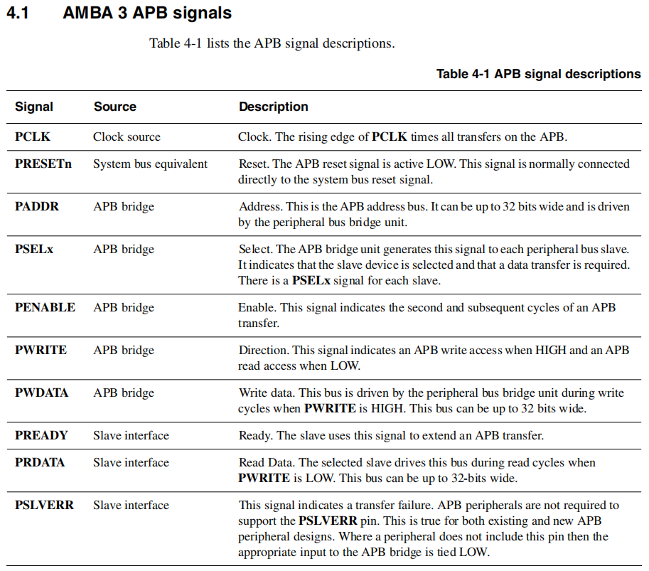
1.1 信号列表
1.2 写传输
写传输分为两种:
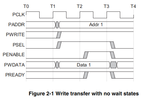
- Write with no wait states
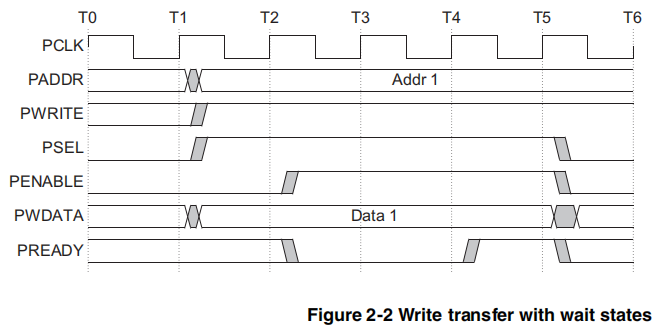
- Write with wait states
1.2.1 Write with no wait states
1.2.2 Write with wait states
1.3 读传输
读传输也分为两种:
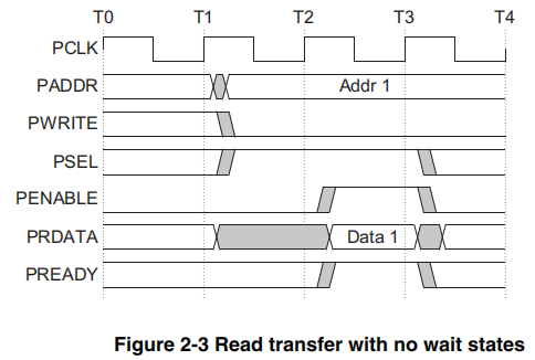
- Read with no wait states
- Read with wait states
1.3.1 Read with no wait states
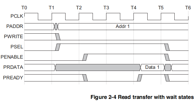
1.3.2 Read with wait states
二、WishBone 总线
WishBone总线有B.3和B.4两个版本,这里使用的是B.4版本。
WishBone 有Classic模式和Pipeline模式,这里介绍Classic模式。
内容截图自参考文献3:wbspec_b4(2.2和3.2章节)
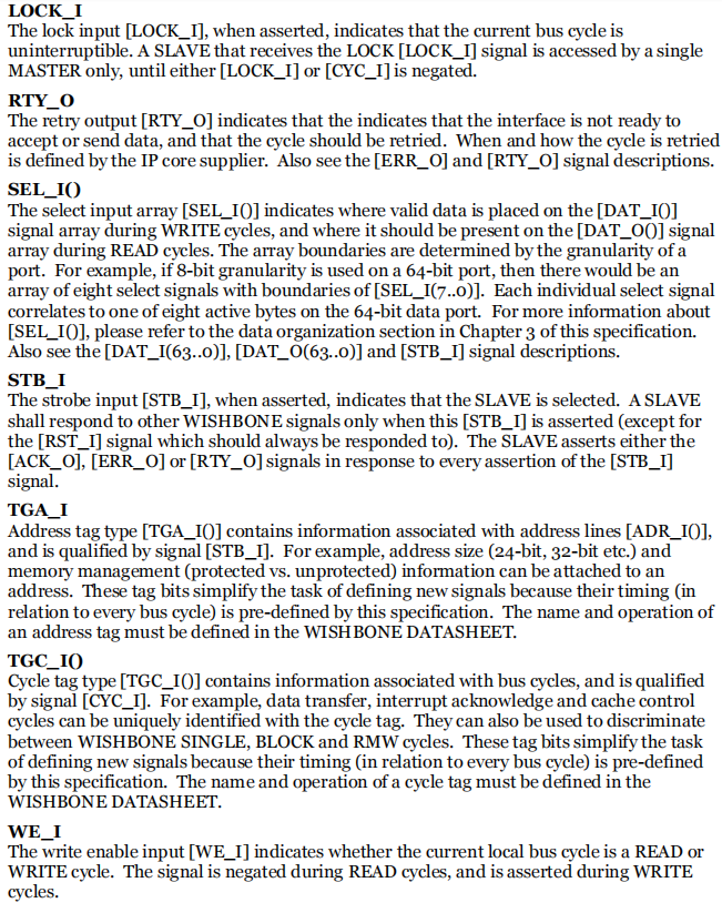
2.1 信号列表
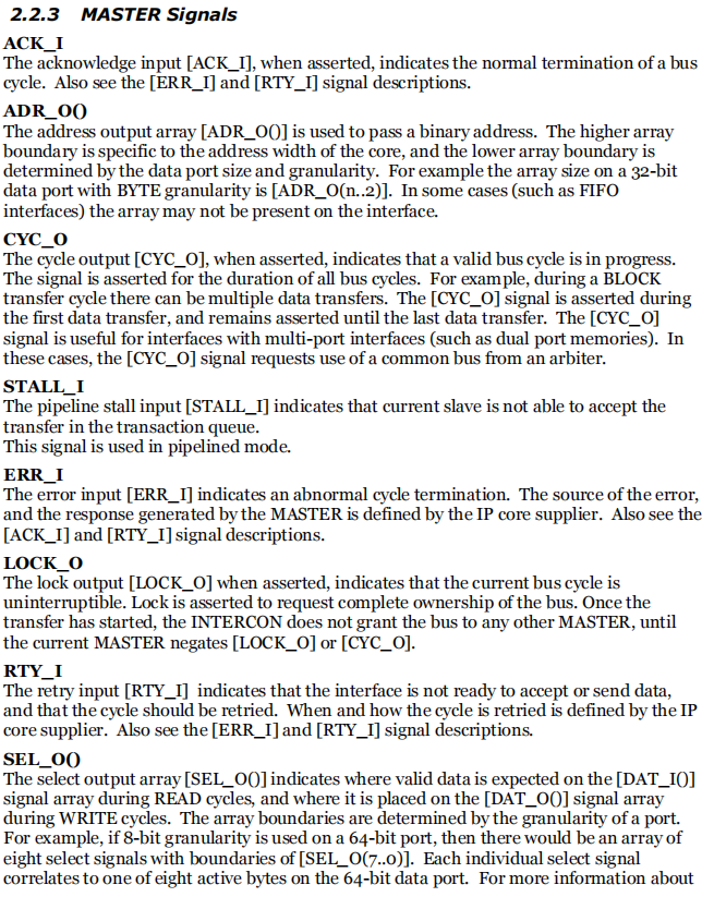
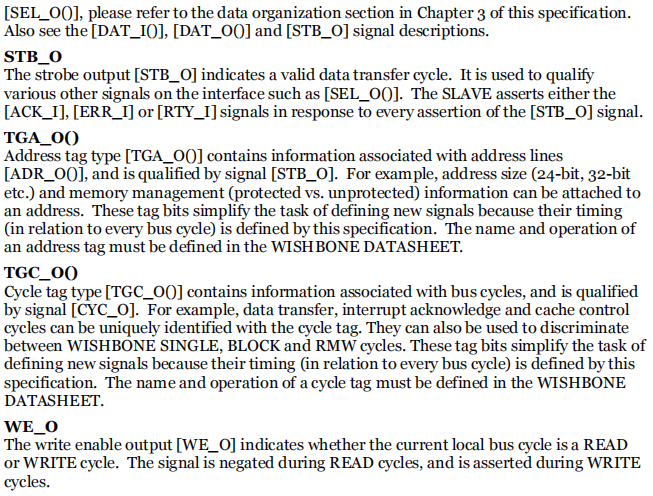
TGA/D/C_O/Ix系列信号,在简化版WishBone总线信号中可能没有。
2.1.1 Master 信号
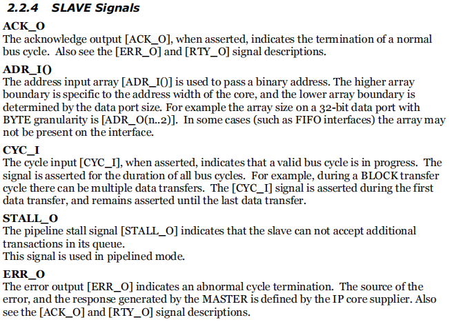
2.1.2 Slave 信号
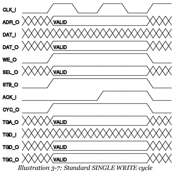
2.2 写传输
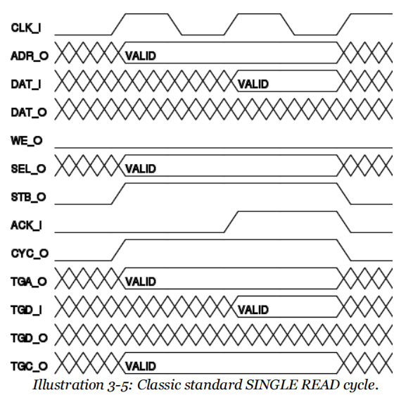
2.3 读传输
三、总线转换
APB总线的结构和WishBone的结构都比较简单,对比他们的读写时序图之后。可以发现只需要简单的连线就可以实现两种总线之间的转换。
信号间的映射关系如下所示:
module apb2wb(
//APB BUS
    input           apb_clk,
    input           apb_rstn,

    input  [31:0]   apb_paddr,
    output [31:0]   apb_prdata,
    input  [31:0]   apb_pwdata,

    input           apb_psel,
    input           apb_penable,
    input           apb_write,
    output          apb_pready,

    output          apb_pslverr,
//WishBone BUS
    output          wb_clk,
    output          wb_rst,

    output [31:0]   wb_addr,
    input  [31:0]   wb_rdata,
    output [31:0]   wb_wdata,

    output          wb_stb,
    output          wb_cyc,
    output          wb_we,
    input           wb_ack,

    output [3:0]    wb_sel

    );

//clk & rst
assign wb_clk = apb_clk;
assign wb_rst = ~apb_rstn;

//data & addr
assign wb_addr = apb_paddr >> 2;
assign wb_wdata = apb_pwdata;
assign apb_prdata = wb_rdata;

//control
assign wb_stb = apb_psel;
assign wb_cyc = apb_psel;

assign wb_we = apb_write;
assign apb_pready = wb_ack;

//other
assign apb_pslverr = 0;
assign wb_sel = 4'b1111;


endmodule
总线位宽需要额外注意。APB使用的是32,IP的WishBone总线默认也是32。但是APB总线不支持WB_sel。所以需要在IP的uart_wb.v的下面两个地方进行修改。
//第一处
always @(posedge clk or posedge wb_rst_i)
	if (wb_rst_i)
		wb_dat_o <= #1 0;
	else if (re_o)
	//change fengbohan
		// case (wb_sel_is)
		// 	4'b0001: wb_dat_o <= #1 {24'b0, wb_dat8_o};
		// 	4'b0010: wb_dat_o <= #1 {16'b0, wb_dat8_o, 8'b0};
		// 	4'b0100: wb_dat_o <= #1 {8'b0, wb_dat8_o, 16'b0};
		// 	4'b1000: wb_dat_o <= #1 {wb_dat8_o, 24'b0};
		// 	4'b1111: wb_dat_o <= #1 wb_dat32_o; // debug interface output
 		// 	default: wb_dat_o <= #1 0;
		//  endcase // case(wb_sel_i)
		wb_dat_o <= #1 {24'b0, wb_dat8_o};

//第二处
//change fengbohan
// assign wb_adr_int = {wb_adr_is[`UART_ADDR_WIDTH-1:2], wb_adr_int_lsb};
assign wb_adr_int = wb_adr_is;
修改后的APB总线32位数据中只有低8位是有效数据,所以读写IP内部寄存器时,寄存器偏移地址需要*4。如下所示:
#define UART_BASE_ADDR 	0X44a00000
#define UART_REG_RBR 	UART_BASE_ADDR + 0X0 *4
#define UART_REG_THR 	UART_BASE_ADDR + 0X0 *4
#define UART_REG_IER 	UART_BASE_ADDR + 0X1 *4
#define UART_REG_IIR 	UART_BASE_ADDR + 0X2 *4
#define UART_REG_FCR 	UART_BASE_ADDR + 0X2 *4
#define UART_REG_LCR 	UART_BASE_ADDR + 0X3 *4
#define UART_REG_MCR 	UART_BASE_ADDR + 0X4 *4
#define UART_REG_LSR 	UART_BASE_ADDR + 0X5 *4
#define UART_REG_MSR 	UART_BASE_ADDR + 0X6 *4
#define UART_REG_SCR 	UART_BASE_ADDR + 0X7 *4

#define UART_REG_DLL 	UART_BASE_ADDR + 0X0 *4
#define UART_REG_DLM 	UART_BASE_ADDR + 0X1 *4
四、开源的UART IP
uart16550IP自带文档,非常详细。
uart16550 is a 16550 compatible (mostly) UART core.
The bus interface is WISHBONE SoC bus Rev. B.
Features all the standard options of the 16550 UART: FIFO based operation, interrupt requests and other.
The datasheet can be downloaded from the CVS tree along with the source code.
附件
- 示例工程文件打包:https://pan.baidu.com/s/17iaKHK5EBE0N_Ayu5IolHw?pwd=ww8y
提取码:ww8y