利用CORDIC IP核计算两路信号的相位差
1 IP 说明
1.1 DDS IP核
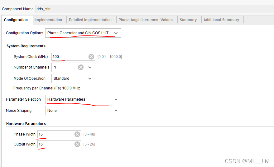
The output frequency(f_out ) , of the DDS waveform is a function of the system clock frequency(f_clk ) .the phase width, that is, number of bits (B ) in the phase accumulator
and the phase increment value (deta_theta) . The output frequency in Hertz is defined by:f_out=f_clkdeta_theta/(2^B)
输出频率的计算公式f_out=f_clkdeta_theta/(2^B)
频率字:deta_theta=f_out*(2^B)/f_clk


1.2 CORDIC IP核
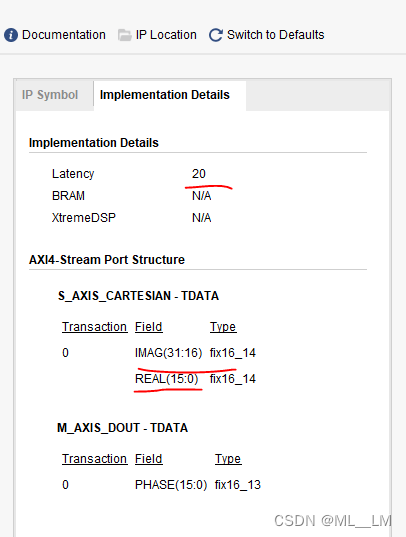
(0)Latency:由这个值可以知道得到输出结果需要多少个时钟。
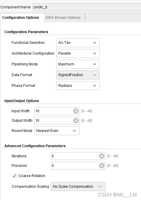
(1)Functional Selection:选择为"Arc Tan"。
(2)architectural configuration:
1)word serial 是为了节省资源,采用了循环的方法,只用一个shift-addsub和一个循环计数器来实现
2)parallel则是用多个shift-addsub串连在一起来实现,如果为了提高始终频率和吞吐量,每个shift-addsub之间 可添加reg ,实现pipeline
(3)Pipelining Mode:可以设置为最大值(Maximum)、最优值(Optimal)和不设置流水线(No pipelining即纯组合逻辑实现)。
增加流水线级数可以提高计算速度。
(4)Data Format:计算arctan时Data Format固定为带符号小数(Signed Fraction)。
(5)Phase Format:可以设置为Radians(以pi为单位)或Scaled Radians(将单位pi归一化到-1~1范围内)。
(6)Input/Output width:设置输入、输出数据位宽
(7)Round mode:舍位模式,这里选择为Nearest Even,表示最接近的值(可以理解为四舍五入)。
(8)Coarse Rotation:默认为勾选。选中此值时,CORDIC的输出范围是-pi~pi;
没有选中时,CORDIC的输出范围是-1/4pi~1/4pi。前者通常更符合我们的需要。


2 源代码
`timescale 1ns / 1ps
/*
知识点:
 1、 DDS IP核
  The output frequency(f_out ) , of the DDS waveform is a function of the system clock frequency(f_clk ) .
  the phase width, that is, number of bits (B )  in the phase accumulator
  and the phase increment value (deta_theta) .
  The output frequency in Hertz is defined by:f_out=f_clk*deta_theta/(2^B)

2、CORDIC IP核
(0)Latency:由这个值可以知道得到输出结果需要多少个时钟。
(1)Functional Selection:选择为"Arc Tan"。
(2)architectural configuration:
    1)word serial 是为了节省资源,采用了循环的方法,只用一个shift-addsub和一个循环计数器来实现
    2)parallel则是用多个shift-addsub串连在一起来实现,如果为了提高始终频率和吞吐量,每个shift-addsub之间 可添加reg ,实现pipeline

(3)Pipelining Mode:可以设置为最大值(Maximum)、最优值(Optimal)和不设置流水线(No pipelining即纯组合逻辑实现)。
                 增加流水线级数可以提高计算速度。
(4)Data Format:计算arctan时Data Format固定为带符号小数(Signed Fraction)。
(5)Phase Format:可以设置为Radians(以pi为单位)或Scaled Radians(将单位pi归一化到-1~1范围内)。

(6)Input/Output width:设置输入、输出数据位宽
(7)Round mode:舍位模式,这里选择为Nearest Even,表示最接近的值(可以理解为四舍五入)。

(8)Coarse Rotation:默认为勾选。选中此值时,CORDIC的输出范围是-pi~pi;
                 没有选中时,CORDIC的输出范围是-1/4pi~1/4pi。前者通常更符合我们的需要。

*/
module top(
    input   clk   , //system clock
    input   rst_n
);


//-----------------------1、产生输入信号
// ------------根据IP核的summery, phase width=16 bits   Frequency per channel=100MHz
// 输出频率的计算公式f_out=f_clk*deta_theta/(2^B)
// 频率字:deta_theta=f_out*(2^B)/f_clk      ,对应输出频率10M
 wire [15 : 0] PINC;
// assign PINC=16'd6554;//10M
  assign PINC=16'd655;//1M
 wire data_tvalid   ;
 wire  [31 : 0]  data_tdata    ;
 dds_sin Inst_dds_sin (
  .aclk(clk),                                  // input wire aclk
  .s_axis_config_tvalid(1'b1),  // input wire s_axis_config_tvalid
  .s_axis_config_tdata(PINC),    // input wire [15 : 0] s_axis_config_tdata

  .m_axis_data_tvalid   (data_tvalid    ),      // output wire m_axis_data_tvalid
  .m_axis_data_tdata    (data_tdata     ),        // output wire [31 : 0] m_axis_data_tdata
  .m_axis_phase_tvalid  (   ),    // output wire m_axis_phase_tvalid
  .m_axis_phase_tdata   (   )      // output wire [15 : 0] m_axis_phase_tdata
);
wire [15:0] RtI;
wire [15:0] RtQ;
assign  RtQ   =data_tdata[31:16];
assign  RtI   =data_tdata[15:0];


//---------------2、计算输入信号RtQ和RtI,两者之间的相位差--arctan(Y/X)=arctan(RtQ/RtI)
//   CORDIC的IP核的输入数据:包括Y和X两个数据输入,共同占用s_tdata总线,Y占用高字节部分,X占用低字节部分。
//   比如输入数据位宽为16Bits时,15~8位为Y,7~0位为X。CORDIC计算arctan(Y/X),输出计算结果
//   仿真结果:phase=atand(32765/253)=90度
wire phase_data_tvalid;
wire [15 : 0]  phase_data;

cordic_0 your_instance_name (
  .aclk(clk),                                        // input wire aclk
  .s_axis_cartesian_tvalid(data_tvalid),  // input wire s_axis_cartesian_tvalid
  .s_axis_cartesian_tdata({RtQ,RtI}),    // input wire [31 : 0] s_axis_cartesian_tdata

  .m_axis_dout_tvalid(phase_data_tvalid),            // output wire m_axis_dout_tvalid
  .m_axis_dout_tdata(phase_data)              // output wire [15 : 0] m_axis_dout_tdata
);


endmodule
`timescale 1ns / 1ps

module sim_top;

reg   clk   ; //system clock
reg   rst_n ;

top Inst_top(
    .clk  (clk  ) , //system clock
    .rst_n(rst_n)
);


initial
begin
    rst_n<=1'b0 ;
    clk<=1'b0   ;
    #10
    rst_n<=1'b1 ;
end

always #5 clk=~clk;//100MHz


endmodule
3 结果分析

仿真结果:phase=atand(32765/253)=90度 ,DDS的实部和虚部理论上相差90度,正确。
