МЦЭјжавЛИіНЯЮЊШыУХЕФЪЕбщ,ЪЙгУCisco Packet TracerЙЄОпХфжУОВЬЌТЗгЩ,ЯъЯИЙ§ГЬгУcsdnМЧТМвЛЯТЁЃ
ЯШНЈСЂМђЕЅЕФЭиЦЫ
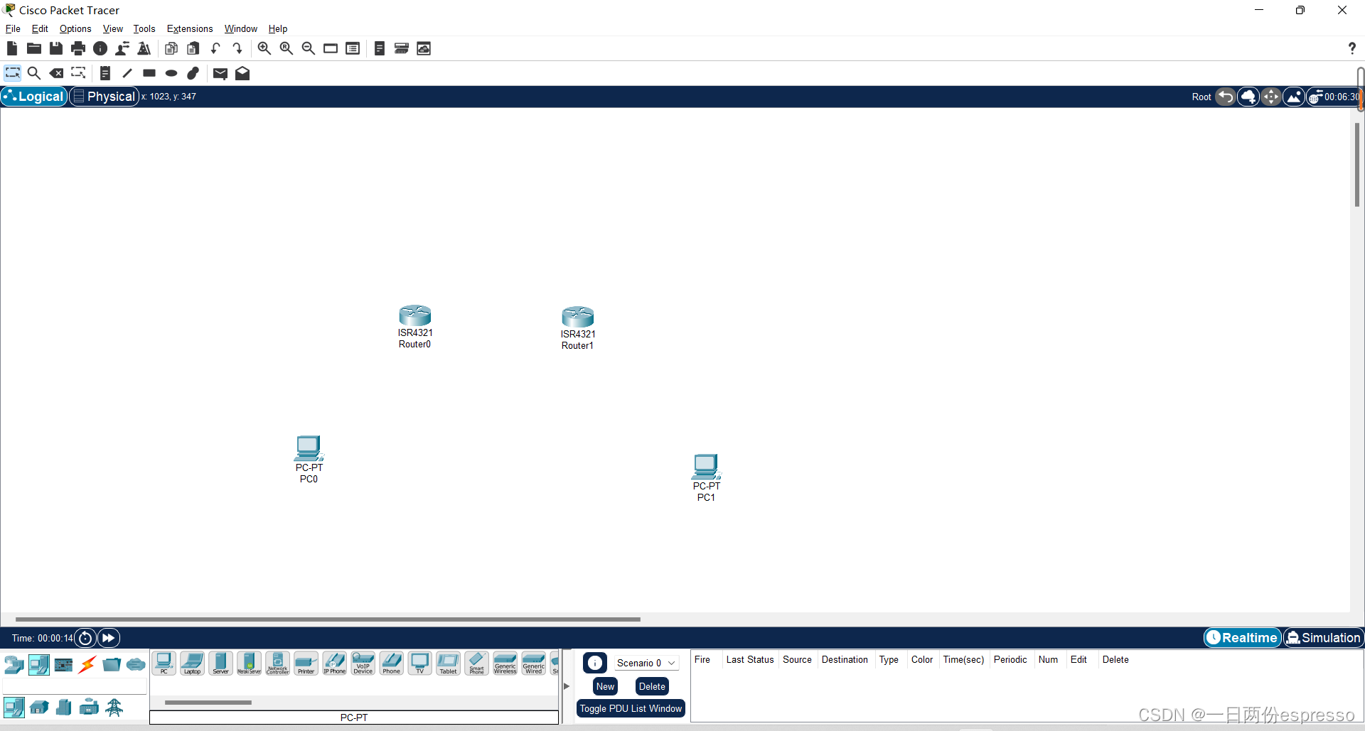
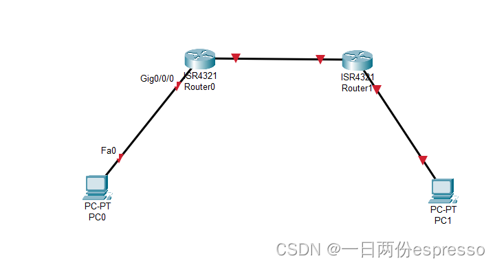
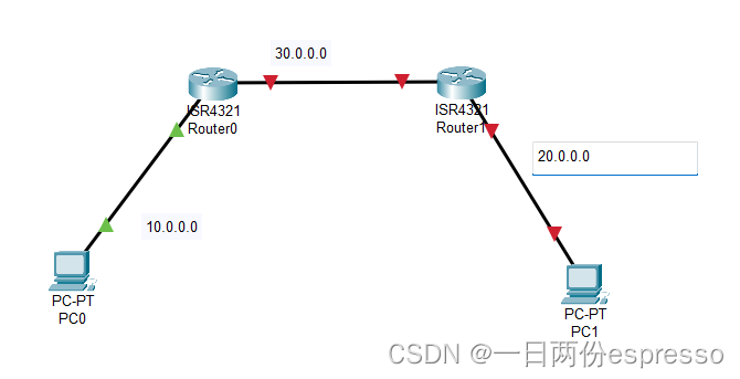
ЮЊЗНБуХфжУIPКЭНЈСЂТЗгЩБэ,ВЩгУзѓСугввЛЕФЗНЪНХфжУЁЃ
ХфжУСНЬЈPCЕФIP,вдPC0ЮЊР§
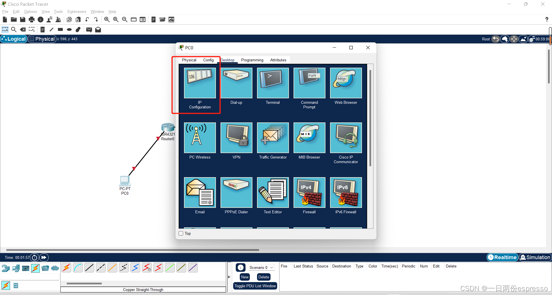
ЕЅЛїPC0,НјШыDesktopжаЕФIP ConfigurationФЃЪНЁЃ
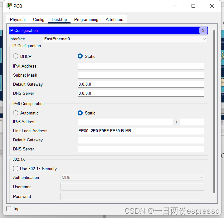
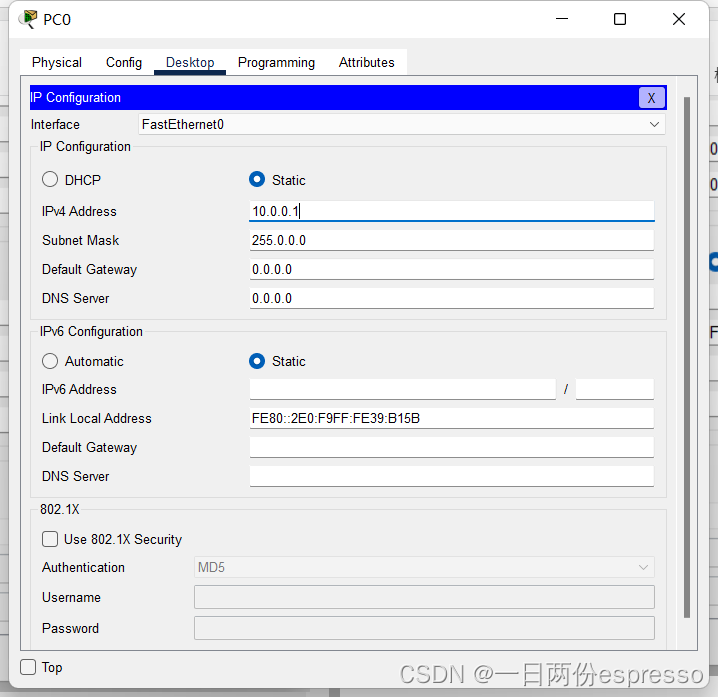
ЩшжУ,IP AddressЮЊ10.0.0.1,згЭјбкТыЛсздЖЏЩњГЩ(255.0.0.0,ЕБШЛЩшжУЮЊ255.255.255.0вВУЛгаЮЪЬт,вђЮЊДЫДІЕФЭјЖЮНіВЩгУСЫЕуЗжЪНЕФЕквЛЖЮ(ЧААЫЮЛ)НјааХфжУ)ЁЃДЫДІЩшжУЮЊ10.0.0.1вВЪЧШЫЮЊЩшжУЕФ,РэТлЩЯЩшжУЮЊЖрЩйЖМПЩвд,ДЫДІвд10.0.0.1ЮЊР§,ЙЪPC0гыТЗгЩЦїRouter0ЕФgi0/0/0ЙЙГЩ10.0.0.0ЭјЖЮЁЃЩшжУPC0ЕФDefault Gateway(ФЌШЯЭјЙи)ЮЊ10.0.0.2ЁЃ
ХфжУPC1ЕФIPЮЊ20.0.0.1,ДЫДІТд,гыЩЯЭЌЁЃ
ЯТУцХфжУСНИіRouterНгПкДІЕФIPЕижЗ
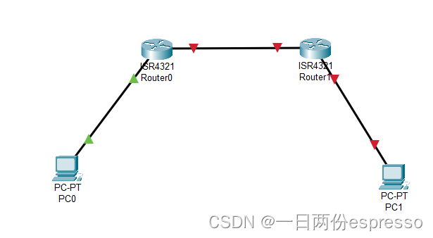
ЯШХфжУзѓБпЕФRouter0
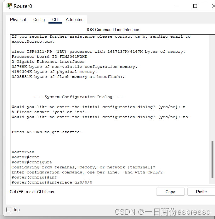
ЕЅЛїRouter0НјШыCLIУќСюааФЃЪНЁЃ
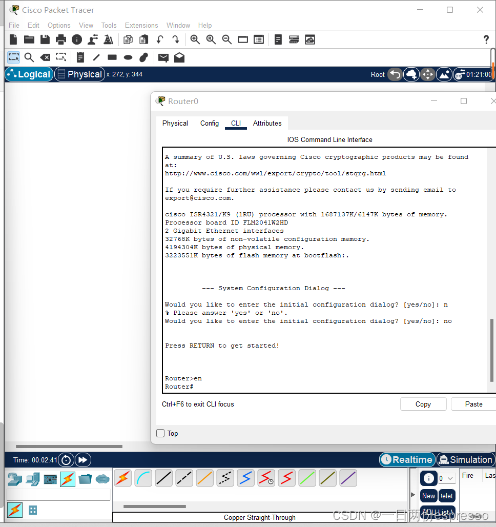
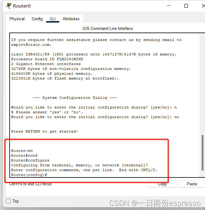
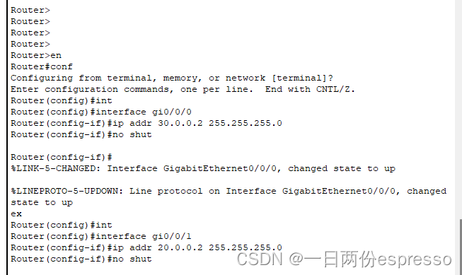
ЪфШыen,Лђenable,НјШы#ФЃЪН,жЎКѓПЊЪМХфжУСНВрНгПкЕФIPЕижЗ,ЯШЪфШыconfЛђconfigure,НјШыconfigФЃЪН(ЪфШыconfЛсздЖЏВЙШЋ,АДTABМќПЩвдЪжЖЏВЙШЋ)ЁЃ
ЪЙгУinterfaceжИСю,ЯШХфжУзѓВргы10ЭјЖЮЯрСЌЕФНгПк,МДgi0/0/0ЁЃ
гЩгкзѓВрЮЊ10ЭјЖЮ,вђДЫipЕижЗЕФИёЪНБиаыЪЧ10.0.0.X,ЖЮФкЧАзКБиаыЯрЭЌ,КѓзКБиаыВЛЭЌ,гЩгкPC0вбХфжУЦфIPЮЊ10.0.0.1,ЙЪrouter0ЕФgi0/0/0НгПкЕФIPжЛФмХфЮЊ10.0.0.1вдЭтЕФIP,Шч10.0.0.2,ДЫДІХфжУЮЊ10.0.0.2ЁЃ
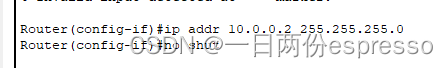
ЪЙгУip addr 10.0.0.2 255.255.255.0ХфжУетИіНгПкЕФIP,ip addrКѓУцНгСНИіЕуЗжЪЎНјжЦЕижЗ,ЗжБ№ЪЧIPЕижЗКЭзгЭјбкТыЁЃ
зюКѓЪфШыno shutжИСюМЄЛю,gi0/0/0НгПкМДХфжУГЩЙІ,ЪЙгУexЭЦГіconfig-ifЁЃ
ПЩвдПДЕН,ДЫЪБPC0КЭRouter0жЎМфОЭНгЭЈСЫЁЃ
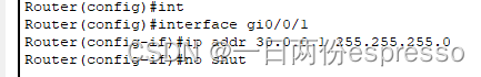
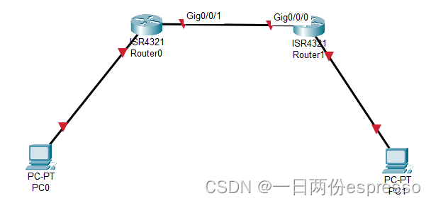
зЊЖјХфжУRouter0ЕФгвВрgi0/0/1НгПк,ЩшжУЦфipЮЊ30.0.0.1ЁЃ
ЪЙгУЮФБОПђБъМЧЮвУЧЧАУцШЫЮЊжИЖЈЕФЭјЖЮЁЃ
дйХфжУгвБпЕФRouter1
ЭЌбљЯШНјШыCLIФЃЪН,жЛВЛЙ§Router1ЕФgi0/0/0(зѓ0гв1,вђДЫетИіНгПкдк30ЭјЖЮФк,гЩгк30.0.0.1вбБЛеМгУ,ЩшжУЫќЮЊ30.0.0.2,ЖјгвБпдк20ЭјЖЮФк,ЩшжУЮЊ20.0.0.2(ЭЌбљЪЧвђЮЊ20.0.0.1вбБЛPC1еМгУ))
ДЫДІПьЫйЙ§вЛЯТ:
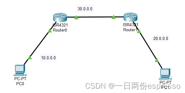
етбљ,ећИіЭиЦЫжаЕФIPЕижЗОЭХфКУСЫЁЃ
ЕЋЪЧ,IPХфКУОЭНсЪјСЫТ№?етбљОЭФмЙЄзїСЫТ№?
ЩшжУТЗгЩБэ
ЮЊСЫЫЕУїДЫЪБЕФЭиЦЫШдШЛЪЧЁАгаШБЯнЕФЁБ,ЮвУЧгУPC0РДpingвЛЯТPC1ЁЃ
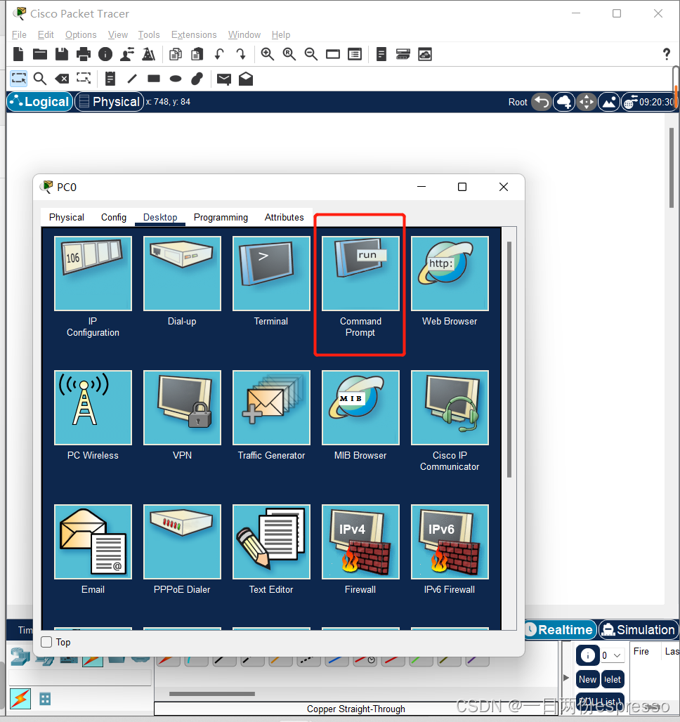
ДђПЊPC0ЕФCommand PromptНјШыУќСюааФЃЪНЁЃ
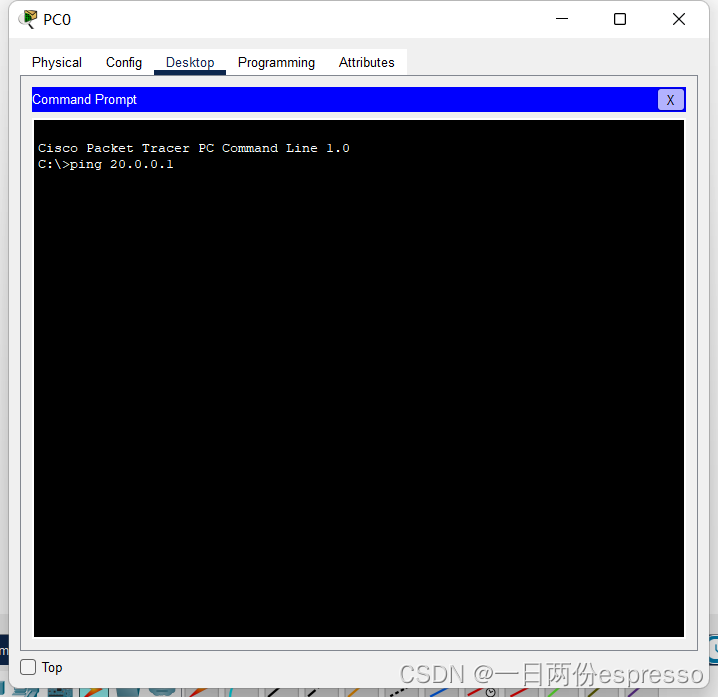
pingвЛЯТPC1ЕФIPЕижЗЁЃ
ПЩвдПДЕН,НсЙћЮЊunreachable,Жј10.0.0.2ПЩвдpingЭЈ,ЫЕУїЭјЖЮФкПЩвде§ГЃЭЈаХ,ЕЋЭјЖЮЭтВЛПЩДяЁЃ
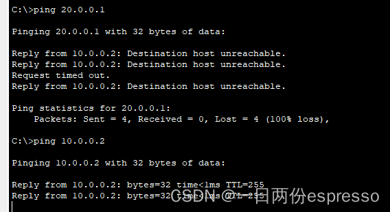
двђдкгкЕБЧАЕФТЗгЩБэЮЊПе,ЛЙашвЊХфжУвЛЯТТЗгЩБэ,МДгЩФПЕФЭјЖЮКЭЯТвЛЬјЕижЗзщГЩЕФЖўдЊзщЁЃ
ЯШХфжУRouter0ЕФТЗгЩБэ
НјШыCLIЕФconfigФЃЪНЁЃ

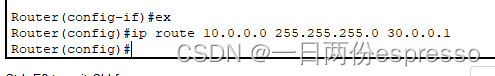
ЪЙгУip routeУќСюИќаТТЗгЩБэ,ЕквЛИіВЮЪ§ЮЊФПБъЭјЖЮ,ЯдШЛЮвУЧЕФФПЕФЕиЪЧ20ЭјЖЮ,ЕкЖўИіВЮЪ§ЮЊзгЭјбкТы,УЛЪВУДКУЫЕЕФ,ЕкШ§ИіВЮЪ§ЮЊЯТвЛЬјЕижЗ,МДЯывЊШЅФПЕФЭјЖЮ,ЕБЧАБЈЮФашвЊЯШЕНФФЁЃгІИУЯШЕНRounter1ЕФзѓВрНгПк,МДIPЕижЗЮЊ30.0.0.2ЕФФПЕФЕиЁЃ
дйХфжУRounter1ЕФТЗгЩБэ
жЛХфжУСЫRounter0ЛЙУЛЭъ,вђЮЊетбљБЈЮФЫфШЛФмДяЕН20.0.0.1,ЕЋЪЧЗДРЁаХЯЂДг20.0.0.1ГіЗЂ,ЮоЗЈЕНДя10.0.0.1,ЙЪRounter1ЕФТЗгЩБэвВашвЊХфжУЁЃ
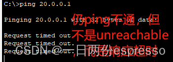
дйping,ЭЈСЫ
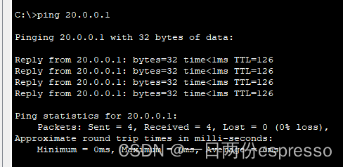
жСДЫ,ОВЬЌТЗгЩЕФЪЕбщБуЭъГЩСЫ,етгІИУЪЧМЦЭјжаЭјТчВузюШыУХЕФЪЕбщЁЃ

