实验需求
1.蓝色方框内设备使用MSTP防环
2.VLAN10的MSTP根桥为LSW1
3.VLAN20的MSTP根桥为LSW2
4.绿色方框内使用VRRP冗余网关
5.VLAN10的VRRP Master为AR1
6.VLAN20的VRRP Master为AR2
实验思路
1.先配置二层接口基础配置和LACP
2.配置MSTP
3.配置各接口地址和VRRP
4.检测是否成功
实验步骤
//最开始先配置二层基础接口和LACP,过于简单,不多赘述。
LSW3设备
//LSW3
sys lsw3
vlan b 10 20
int e 0/0/1
p l a
p d v 10
int e 0/0/2
p l t
p t a v 10
int e 0/0/3
p l t
p t a v 10
//配置边缘端口目的加快收敛
stp edg en
LSW4
//LSW4
sys lsw4
vlan b 10 20
int e 0/0/1
p l a
p d v 20
int e 0/0/2
p l t
p t a v 20
int e 0/0/3
p l t
p t a v 20
stp edg en
LSW1
//lsw1
sys lsw1
vlan b 10 20
int g 0/0/6
p l t
p t a v 10 20
inter eth 12
//配置动态LACP
mode lacp
p l t
p t a v 10 20
trunkport g0/0/1 to g0/0/3
int g 0/0/4
p l t
p t a v 20
int g 0/0/5
p l t
p t a v 10
LSW2
//lsw2
sys lsw2
vlan b 10 20
int g 0/0/6
p l t
p t a v 10 20
inter eth 12
mode lacp
p l t
p t a v 10 20
trunkport g 0/0/1 to 0/0/3
int g 0/0/4
p l t
p t a v 10
int g 0/0/5
p l t
p t a v 20
至此二层接口和LACP已经配置完毕!
我们接下来开始配置蓝色边框内的MSTP生成树协议
所有二三层交换机配置MSTP都相同LSW1/2/3/4
//配置mstp
stp region-configuration
 region-name vlan10
 revision-level 12
 instance 10 vlan 10
 instance 20 vlan 20
 active region-configuration
//配置根桥以满足需求
LSW1
//配置根桥以满足需求
stp instance 10 root primary
stp instance 20 root secondary
LSW2
//配置根桥以满足需求
stp instance 20 root primary
stp instance 10 root secondary
至此MSTP已全部配置完毕!
我们接下来就开始配置各接口地址和VRRP
AR1
//AR1
int g 0/0/1
ip add 192.168.3.1 30
//配置通向环回口的路由,方便检测
ip route-static 8.8.8.8 32 192.168.3.2

interface GigabitEthernet0/0/0.10
//终结vlan10的标签
 dot1q termination vid 10
 //配置接口真实IP地址
 ip address 192.168.1.252 255.255.255.0
 //配置VRRP组名和虚拟IP(每个组公用一个/多个相同的虚拟IP)
 vrrp vrid 10 virtual-ip 192.168.1.254
 //配置接口在VRRP内的优先级
 vrrp vrid 10 priority 120
 //配置抢占时间
 vrrp vrid 10 preempt-mode timer delay 10
 //监视上行端口,很必要!!
 vrrp vrid 10 track interface GigabitEthernet0/0/1 reduced 40
 //开启端口广播,不开启咋互发报文
 arp broadcast enable

interface GigabitEthernet0/0/0.20
 dot1q termination vid 20
 ip address 192.168.2.252 255.255.255.0
 vrrp vrid 20 virtual-ip 192.168.2.254
 arp broadcast enable
AR2和AR1很类似
//AR2
int g 0/0/1
ip add 192.168.3.5 30
//配置通向环回口的路由,方便检测
ip route-static 8.8.8.8 32 192.168.3.6

interface GigabitEthernet0/0/0.10
 dot1q termination vid 10
 ip address 192.168.1.253 255.255.255.0
 vrrp vrid 10 virtual-ip 192.168.1.254
 arp broadcast enable

interface GigabitEthernet0/0/0.20
 dot1q termination vid 20
 ip address 192.168.2.253 255.255.255.0
 vrrp vrid 20 virtual-ip 192.168.2.254
 vrrp vrid 20 priority 120
 vrrp vrid 20 preempt-mode timer delay 10
 vrrp vrid 20 track interface GigabitEthernet0/0/1 reduced 40
 arp broadcast enable
至此我们VRRP已经全部完成配置!
我们最后开始收尾工作,给AR3配置IP地址
AR3
interface GigabitEthernet0/0/0
 ip address 192.168.3.2 255.255.255.252
interface GigabitEthernet0/0/1
 ip address 192.168.3.6 255.255.255.252
 //配置环回口地址,便于检测
interface LoopBack0
 ip address 8.8.8.8 255.255.255.255
AR3配置静态回去的路由
ip route-static 192.168.1.0 255.255.255.0 192.168.3.1
ip route-static 192.168.1.0 255.255.255.0 192.168.3.5
ip route-static 192.168.2.0 255.255.255.0 192.168.3.5
ip route-static 192.168.2.0 255.255.255.0 192.168.3.1
我们所有配置都已经按需求配置完毕!
激动人心时刻,最终测试阶段
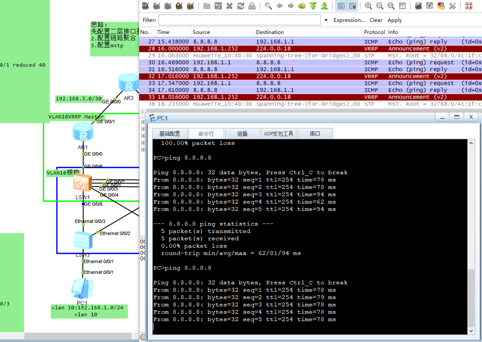
测试vlan10是否已LSW1为根桥进行转发

测试VRRP AR1是否为Master

大家还可以测试VRRP自动切换功能,我这里有点小问题没法测试
VRRP相关配置命令
命令来源于华为官方
1.创建VRRP备份组并给备份组配置虚拟IP地址
//注意:各备份组之间的虚拟IP地址不能重复;同属一个备份组的设备接口需使用相同的VRID。
interface-GigabitEthernet0/0/0] vrrp vrid virtual-router-id  virtual-ip virtual-address
2.配置路由器在备份组中的优先级
//注意:通常情况下,Master设备的优先级应高于Backup设备
interface-GigabitEthernet0/0/0] vrrp vrid virtual-router-id priority priority-value
3… 配置备份组中设备的抢占延迟时间
[interface-GigabitEthernet0/0/0] vrrp vrid virtual-router-id preempt-mode timer delay delay-value
4… 配置VRRP备份组中设备采用非抢占模式
//缺省情况下,抢占模式已被激活。
[interface-GigabitEthernet0/0/0] vrrp vrid virtual-router-id preempt-mode disable
- 配置VRRP备份组监视接口
//可配置设备当检测到上行接口或链路出现故障时,增加或者减少自身优先级,IP地址拥有者和Eth-trunk成员口不允许配置VRRP监视功能
[interface-GigabitEthernet0/0/0] vrrp vrid virtual-router-id track interface interface-type interface-number [ increased value-increased | reduced value-decreased ]
6.配置VRRP备份组联动普通BFD会话
//如果选择参数session-name bfd-configure-name,可以绑定静态BFD会话或者标识符自协商的静态BFD会话。
如果选择参数bfd-session-id,只能绑定静态BFD会话。
[interface-GigabitEthernet0/0/0] vrrp vrid virtual-router-id track bfd-session { bfd-session-id | session-name bfd-configure-name } [ increased value-increased | reduced value-reduced ]

